
Hull form intended for vessels provided with an air cavity

An air cavity, ship technology, used in ship hull, hull design, ship construction, etc.

Active Publication Date: 2011-08-31
STENA REDERI
View PDF12 Cites 0 Cited by
  • Summary
  • Abstract
  • Description
  • Claims
  • Application Information

AI Technical Summary

Problems solved by technology

[0007] All of the above difficulties have so far prevented the principle of the air cavity from having any practical application in conventional ships for ocean-going traffic

Method used


Image

  • Hull form intended for vessels provided with an air cavity
  • Hull form intended for vessels provided with an air cavity
  • Hull form intended for vessels provided with an air cavity

Examples


Embodiment Construction

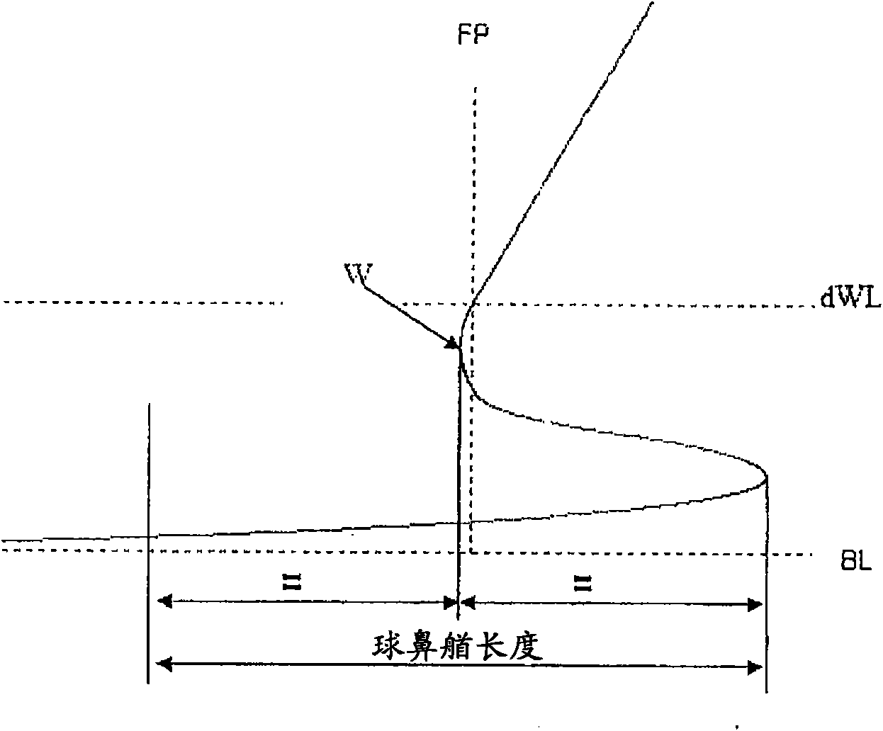
[0058] figure 1 The profile line is shown with the stem defined by the insertion. Baseline (BL) is the line parallel to dWL (design waterline) passing through the lowest point of the ship. The waist (W) of the bow is the most aft point of the bow at a position above the edge of the bow of the bow. In the figures, the bulb length is also defined. This limitation applies to the assumption that all transverse frames have a waist within this length. If this is not the case, the length is reduced from the stem edge of the bulb to the transverse frame, which is the last frame of the fore half of the hull with the waist.

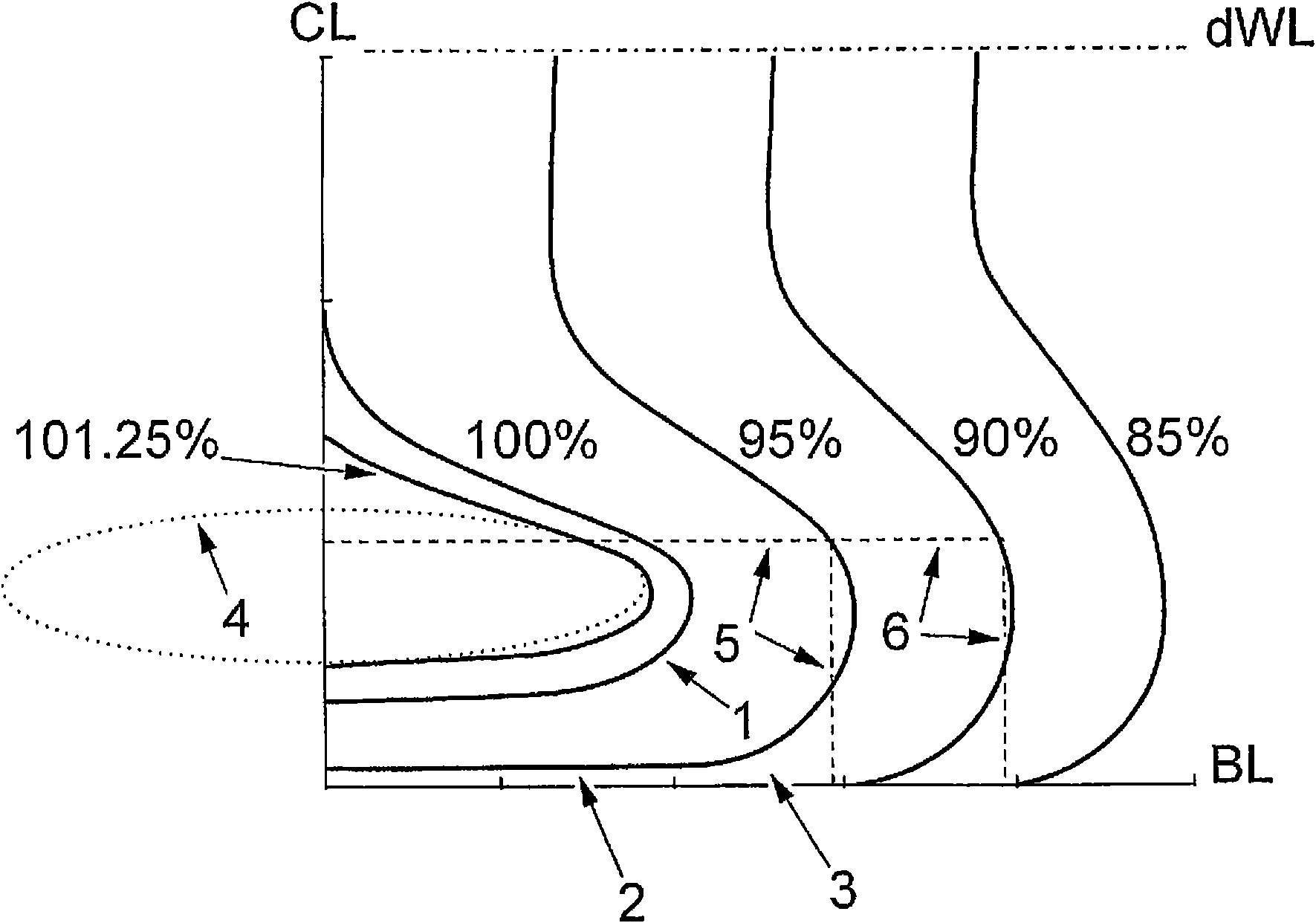
[0059] figure 2 An example of a profile line diagram showing the forward part of the hull up to dWL towards the bow. The frame shown corresponds to 85%, 90%, 95%, 100% and 101.25% of the length of the vertical line. 50% corresponds to amidships, and 100% corresponds to the frame of the forward perpendicular (FP). 101.25% of the length of the perpendicular c...


PUM


Abstract

Disclosed is a hull form for vessels, which gives a great plane bottom area and which is suitable for and can utilize the principle of air cavity. The hull form reduces the wet surface of the hull, decreases the motions at sea and results in a vessel having reduced power need and bunker consumption and which is suitable for ocean-going traffic.

Description

technical field [0001] The invention relates to a hull form for ships. Background technique [0002] One of the most important parameters in all ship construction is the relationship between speed and power. For a typical merchant ship, the frictional resistance, ie the friction between the underwater hull and the water, is a completely dominant part of the total resistance of the ship. Wave resistance becomes critical only when the speed increases, eg for high speed ships. Attempts have been made to influence the frictional resistance by different types of surface structures and by different types of air lubrication. However, results to date for conventional merchant ships have been negative. [0003] Another way to reduce frictional resistance is to reduce the wetted surface area. The wetted surface is the part of the underwater hull that is in contact with the surrounding water at zero velocity. [0004] The wetted surface can be reduced by the implementation of the ...

Claims


Application Information

Patent Timeline
Patent Type & Authority Applications(China)
IPC IPC(8): B63B1/06B63B1/38
CPCB63B1/38Y02T70/126Y02T70/122B63B1/063Y02T70/10B63B1/06
Inventor S·比施泰特
Owner STENA REDERI
Learn More