
Automatic air gun for measuring oil well liquid level

A technology of liquid level measurement and air gun, which is applied in construction and other directions, can solve problems such as complex structure, sound pulse, self-adaptation, etc., and achieve the effect of solving complex structure, simple airway connection and good sealing performance

Inactive Publication Date: 2013-07-31
ZHEJIANG UNIV
View PDF6 Cites 0 Cited by
  • Summary
  • Abstract
  • Description
  • Claims
  • Application Information

AI Technical Summary

Problems solved by technology

[0005] At present, most of the air guns used for oil well liquid level measurement in China are implosion type air guns or external explosion type air guns. This single mode makes the air guns have a pressure application range and cannot adapt to changes in the environment; Air guns are generally also manual air guns, and the transition between implosion and external explosion cannot be performed according to the change of internal origin pressure and continuous detection, which means that automatic control cannot be realized, and pulses cannot be continuously and automatically generated
And the automatic air gun that existing internal and external explosion is integrated is generally divided into internal explosion device and external explosion device, controls two three-way air valves respectively with two pilot deflation solenoid valves, produces sound pulse, and the structure is more complicated

Method used


Image

  • Automatic air gun for measuring oil well liquid level
  • Automatic air gun for measuring oil well liquid level
  • Automatic air gun for measuring oil well liquid level

Examples


Embodiment Construction

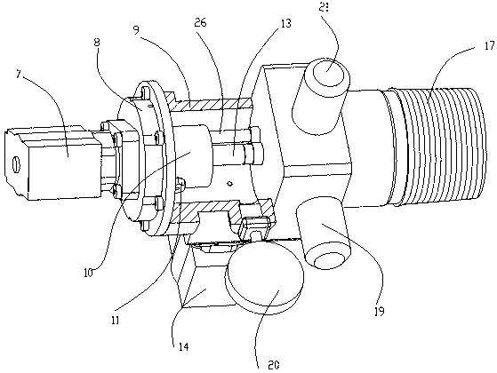
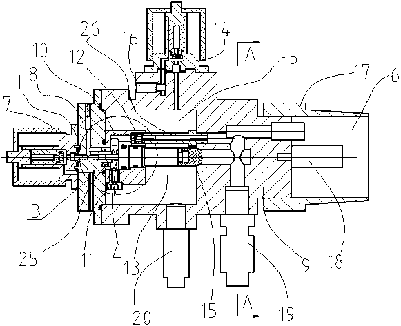
[0030] According to the principles of the cartridge valve and the differential pressure area method, the present invention adopts a four-step stepped design for the main valve stem of an ordinary air gun, and introduces two air source pressures at the force-bearing end of the air source, so that one end of the air gun is both affected by the internal pressure. The gas pressure of the gas source is also affected by the gas pressure of the external gas source, so that no matter whether the internal gas source is a high-pressure gas source or the external gas source is a high-pressure gas source, there is a high-pressure gas source as the driving gas source for the main valve stem, and The other end of the main valve stem introduces high-pressure gas through the damping channel, and adopts the differential pressure area method, so that the force bearing area of ​​the main valve stem control chamber end is larger than the force bearing area of ​​the gas source end, so the total forc...


PUM


Abstract

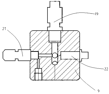
The invention discloses an automatic air gun for measuring oil well liquid level. The automatic air gun for measuring oil well liquid level comprises a pilot deflation electromagnetic valve, a valve cover, a valve body, a main valve combination arranged in the valve body, an adjusting spring, an inflation / deflation electromagnetic valve and a wellhead connector, wherein one side of the valve bodyis provided with the valve cover; the pilot deflation electromagnetic valve is arranged on the valve cover; the other side of the valve body opposite to the pilot deflation electromagnetic valve is provided with the wellhead connector; the side of the valve body in the wellhead connector is provided with a microphone; the valve body is further provided with a pressure sensor, a pressure gauge, a micro-sound sensor, a manual pressure relief valve and the inflation / deflation electromagnetic valve. A main valve rod is designed to be a stepped type, so that gas in a well and gas in a gas storage chamber both can be used as the gas sources for pushing the valve rod to move, and the implosion and explosion manners are combined together; the two gas sources are connected with a control cavity bydamping holes for inflating the control cavity, so that gas resetting of the main valve rod can be realized, continuous transmission also can be realized when PMW (pulse width modulation) signals aresupplied to the pilot deflation electromagnetic valve; the shortage that the traditional implosion / explosion air gun has a complicated structure and is difficult to assemble and disassemble is solved.

Description

technical field [0001] The invention relates to an automatic air gun for oil well liquid level measurement during oil well development. Background technique [0002] As we all know, the determination of oil well liquid level is of great significance to oil well survey and measurement, and it can be an auxiliary parameter to determine oil well production, permeability and other parameters. [0003] Echo ranging has been widely used in oil well measurement. By generating a sound pulse at the wellhead, the pulse propagates downhole through the annulus between the tubing and the casing. By measuring the time of coupling echo and liquid level echo, that is Acoustic velocity and liquid surface depth can be obtained. The traditional way of generating sound pulses is acoustic bombs. Due to many factors such as safety and environmental protection, it has become a trend to replace acoustic bombs with air guns. [0004] There are two kinds of air sources for the sound pulse of the air...

Claims


Application Information

Patent Timeline
Patent Type & Authority Patents(China)
IPC IPC(8): E21B47/047
Inventor 陶国良刘琼刘昊孟德远班伟张峰
Owner ZHEJIANG UNIV
Learn More