Method for conveying material by using screw conveyer

A screw conveying device and material conveying technology, which is applied in packaging and other directions, can solve problems such as material blockage, achieve the effect of improving conveying capacity, improving production efficiency, and reducing the number of shutdowns for cleaning

Active Publication Date: 2014-01-22
COFCO GROUP +1
View PDF3 Cites 0 Cited by
  • Summary
  • Abstract
  • Description
  • Claims
  • Application Information

AI Technical Summary

Problems solved by technology

[0003] In order to overcome the defect that the screw conveying device is prone to material clogging during operation in the existing solid particle conveying method, the present invention provides a method for conveying materials using a screw conveying device that is not prone to material clogging

Method used


Image

  • Method for conveying material by using screw conveyer
  • Method for conveying material by using screw conveyer
  • Method for conveying material by using screw conveyer

Examples


Embodiment 1

[0029] This embodiment is used to illustrate the method for conveying materials using a screw conveyor provided by the present invention.

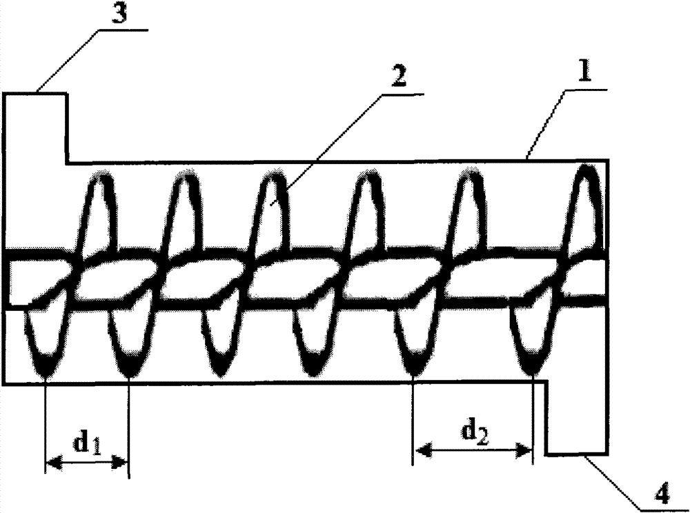
[0030] The LS500 type screw conveying device purchased from Botou Maite Cement Machinery Co., Ltd. is improved. The screw conveying device includes a shell, a screw propeller, a driving device, a feed port and a discharge port. In the improved screw conveying device, the screw propeller is composed of a central shaft and 7 spiral blades, the axial length of the central shaft is 3.07 meters, and the diameter of the outer edge of the spiral blades of the screw propeller is all 500 mm, the distance between the outer edge of the spiral blade and the casing is 20 mm, and the pitch between the first spiral blade and the second spiral blade is 400 along the material advancing direction in the spiral conveying device Mm, the pitch between the following spiral blades increases by 35 mm.

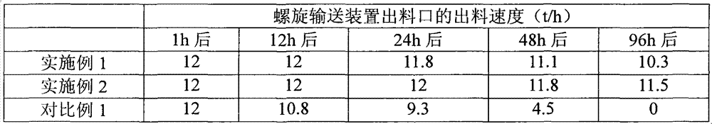
[0031] Using the above-mentioned improved screw conveying device...

Embodiment 2

[0033] This embodiment is used to illustrate the method for conveying materials using a screw conveyor provided by the present invention.

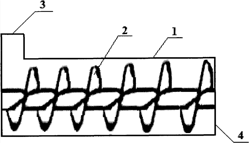
[0034] The LS500 type screw conveying device purchased from Botou Maite Cement Machinery Co., Ltd. is improved. The screw conveying device includes a shell, a screw propeller, a driving device, a feed port and a discharge port. In the improved screw conveying device, the screw propeller is composed of a central shaft and 7 spiral blades. The shaft length of the central shaft is 3.07 meters, and the diameter of the inner wall of the shell is 550 mm. In the advancing direction of the screw conveying device, the diameter of the outer edge of the first spiral blade is 450 mm, and the diameter of the outer edge of the subsequent spiral blades increases by 10 mm; the first spiral blade and the second spiral blade The pitch between the helical blades is 400 mm, and the pitch between the following spiral blades is increased by 35 mm.

[0035] Using th...


PUM


Abstract

The invention discloses a method for conveying a material by using a screw conveyer. The screw conveyer comprises a shell (1) and a screw propeller (2) placed in the shell (1); a material inlet (3) and a material outlet (4) are formed at two ends of the shell (1) respectively; and the screw propeller (2) comprises a shaft and at least three screw blades. Each screw blade comprises a first part and a second part, the screw blades of the first part are the screw blades close to the material inlet (3), the screw blades of the second part are the screw blades close to the material outlet (4), and the screw pitch of the screw blades of the second part is larger than that of the screw blades of the first part. The method comprises the following steps: adding the material into the shell (1) through the material inlet (3) and conveying the material to the material outlet (4) through the screw propeller (2). The method for conveying the material by using the screw conveyer can be used for remarkably overcoming the problem of material blockage in the shell.

Description

Technical field [0001] The invention relates to a method for conveying materials using a screw conveying device. Background technique [0002] Screw conveyors are widely used in the conveying process of solid particles in various fields. The screw conveying device used in the existing solid particle conveying method usually includes a shell, a screw propeller, a feed port and a discharge port; the screw propeller is located in the shell, and the feed port and the discharge port are located in the shell. The two ends of the body; the screw propeller includes a shaft and a spiral blade located on it. There is a gap between the outer edge of the spiral blade and the inner wall of the casing; and all the spiral blades form the same pitch. The screw conveying device has a gap between the outer edge of the screw blade and the inner wall of the housing. Therefore, as the screw blade advances forward when conveying solid particles, the solid particles fall onto the inner wall of the hou...

Claims


Application Information

Patent Timeline
Patent Type & Authority Patents(China)
IPC IPC(8): B65G33/14B65G33/24B65G33/26
Inventor 岳国君柳树海张均业王利邓立康
Owner COFCO GROUP
Why Eureka
Try Eureka