Device for controlling the fluid supply of a system

A technology of control device and control pipe, which is applied in the direction of valve operation/release device, control valve, valve device, etc., can solve the problem of no supply of nozzles, etc., achieve the effect of reduced fluid consumption and simple device design

Active Publication Date: 2011-08-24
BONTAZ CENT
View PDF5 Cites 8 Cited by
  • Summary
  • Abstract
  • Description
  • Claims
  • Application Information

AI Technical Summary

Problems solved by technology

Therefore, when the engine is running at low speed, the pressure of the cooling fluid is less than the pressure at which the valve opens, and the nozzles are not supplied

Method used


Image

  • Device for controlling the fluid supply of a system
  • Device for controlling the fluid supply of a system
  • Device for controlling the fluid supply of a system

Examples


Embodiment Construction

[0028] In the following description, the example used to illustrate the invention will be the supply of cooling nozzles; nevertheless, the invention is applicable to all fields where fluids are used and their supply needs to be controlled.

[0029] Also, for simplicity, we will use the term “oil” when referring to hydraulic cooling fluids. However, it should be noted that the invention is not limited to the use of oil, and any hydraulic fluid capable of reducing the temperature of the piston may be suitable.

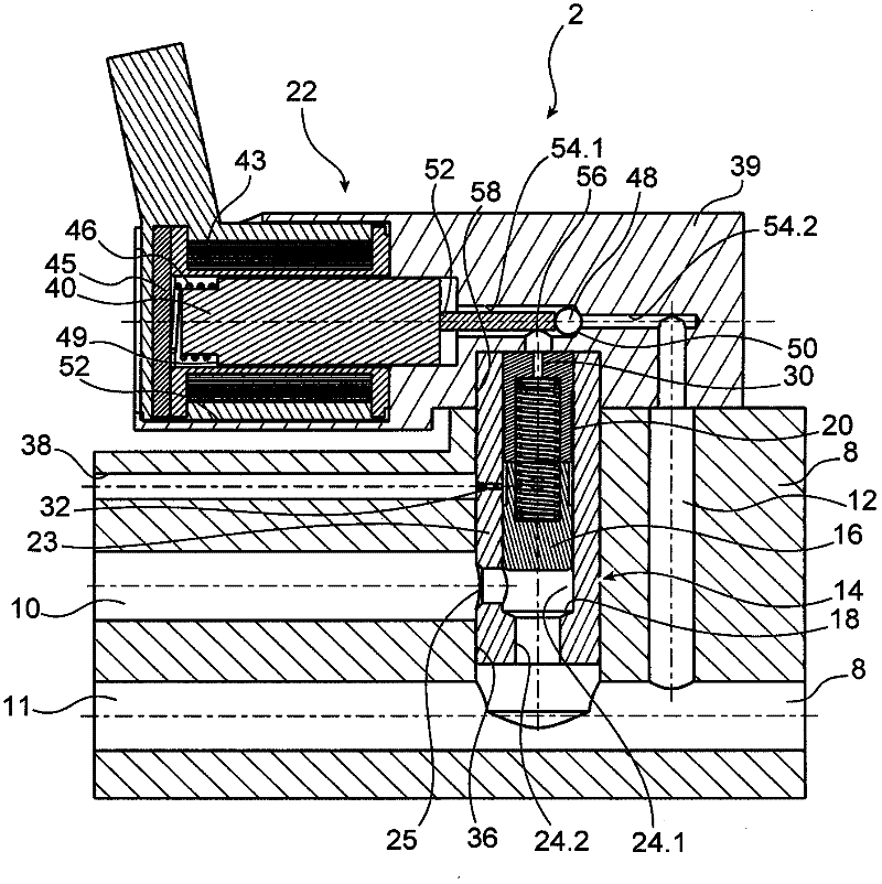
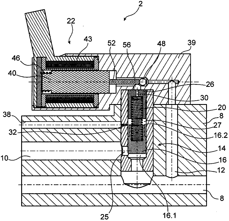
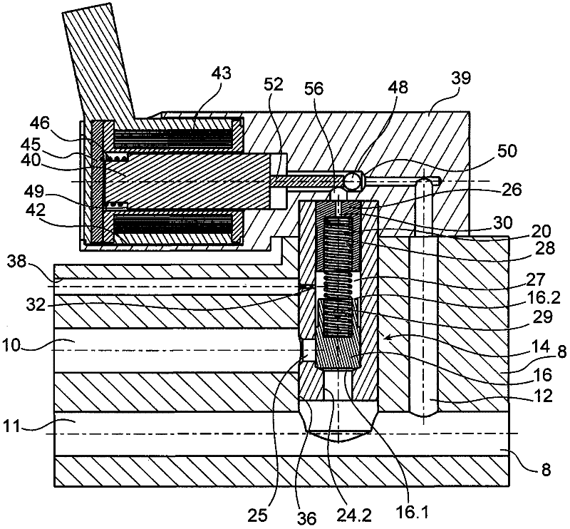
[0030] In FIGS. 1 to 3B an exemplary embodiment of a control device according to the invention can be seen.

[0031] The control device 2 according to the present invention is to be installed between a pressurized oil source 3 (symbolized in FIG. 4 ) and at least one oil nozzle 4 (symbolized in FIG. 4 ), the oil nozzle 4 is to be directed towards an internal combustion Oil is sprayed from the bottom of the engine's multiple pistons (not shown). The control device 2 con...


PUM


Abstract

The invention relates to a system for cooling the pistons of an internal combustion engine, comprising an oil pump driven by the engine, nozzles for spraying oil on the pistons, and a control device (2) provided between the oil pump and the nozzles, the control device including a valve (14) arranged between an oil inlet duct (8) connected to the pressurised oil pump and a nozzle supply duct (10), said valve (14) enabling the oil flow from the pump to the nozzles when the oil pressure is at least equal to a threshold pressure, wherein said device further comprises an electrovalve (22) capable of closing the valve (14) while enabling the pressurised oil to contact the plug (16) in the closing direction of the valve (14).

Description

technical field [0001] The present invention relates to a device for controlling the supply of fluid to a system, for example the supply of oil to nozzles for cooling the pistons of an internal combustion engine. Background technique [0002] Cooling nozzles enable cooling fluid such as oil to be sprayed towards the bottom of the piston. [0003] Cooling fluid is delivered under pressure to the nozzles, which vaporize the fluid as it hits the piston. Pressurization is achieved with a hydraulic pump driven directly by the engine. [0004] There are two types of such nozzles: [0005] - the nozzles of the first type continuously inject oil to the bottom of the piston irrespective of the operating conditions of said engine, [0006] - The second type of nozzle comprises a valve which opens only when the pressure of the cooling fluid reaches a certain critical value. The valve is formed by a piston and a spring, wherein the piston cooperates with a seat to prevent the passag...

Claims


Application Information

Patent Timeline
Patent Type & Authority Applications(China)
IPC IPC(8): F01P3/10F16K15/18F16K17/10
CPCF01P3/10F01P3/08F16K31/423F16K31/0675F16K17/04F16K15/044
Inventor 斯蒂芬·佩特罗克里斯多佛·拉格托玛琳·曼金
Owner BONTAZ CENT
Why Eureka
Try Eureka