Wiper arrangement and compressor with such a wiper arrangement

A technology of oil scraping device and compressor, which is applied in the direction of mechanical equipment, engine components, engine sealing, etc., to achieve the effects of reducing wear, improving oil scraping effect, and good oil scraping effect

Inactive Publication Date: 2011-08-24
HOERBIGER KOMPRESSORTECHNIK HLDG GMBH
View PDF14 Cites 4 Cited by
  • Summary
  • Abstract
  • Description
  • Claims
  • Application Information

AI Technical Summary

Problems solved by technology

What these piston ring devices have in common is that the L-shaped ring is independent of the ring set in it and can be lifted from the sealing surface (here, the cylinder wall), thereby forming an oil scraping edge, which from May be undesirable from a minimum oil spill point of view

Method used


Image

  • Wiper arrangement and compressor with such a wiper arrangement
  • Wiper arrangement and compressor with such a wiper arrangement
  • Wiper arrangement and compressor with such a wiper arrangement

Examples


Embodiment Construction

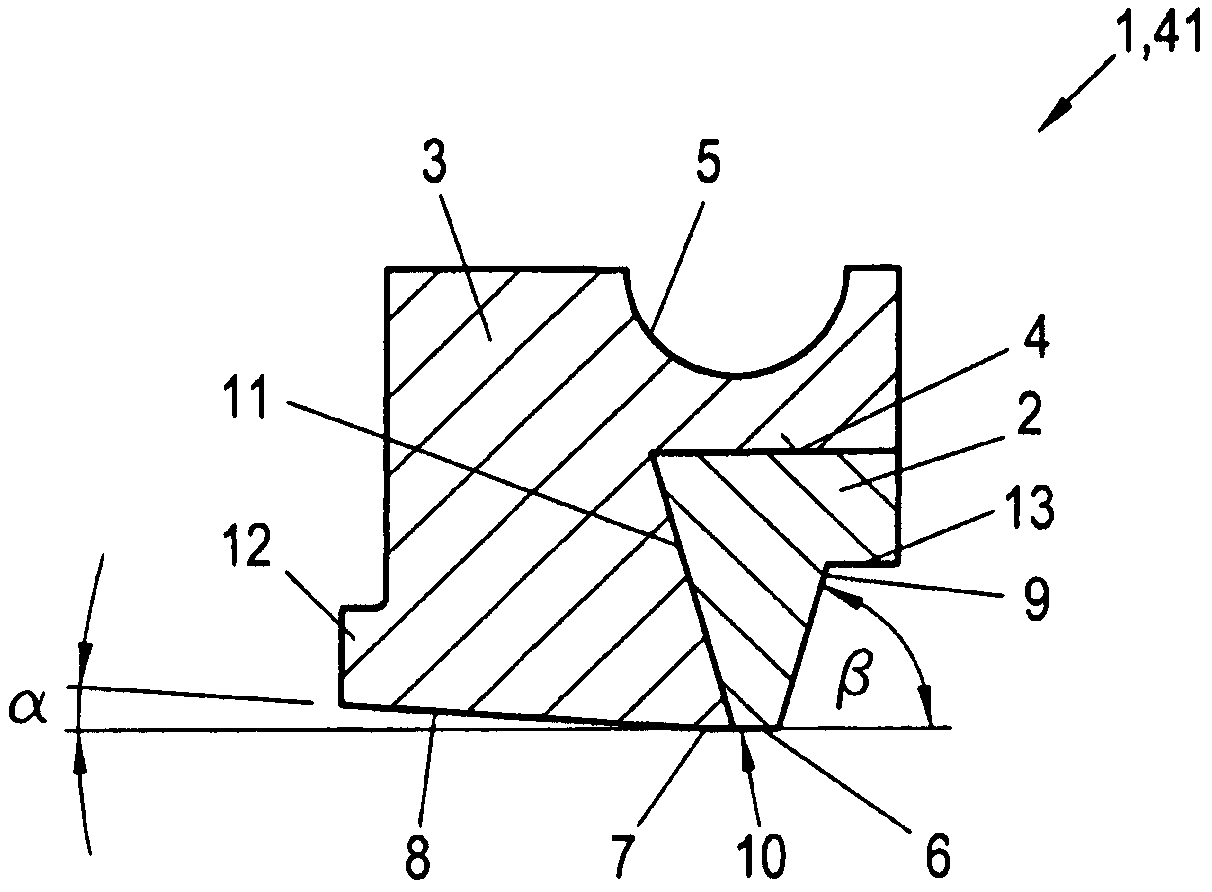
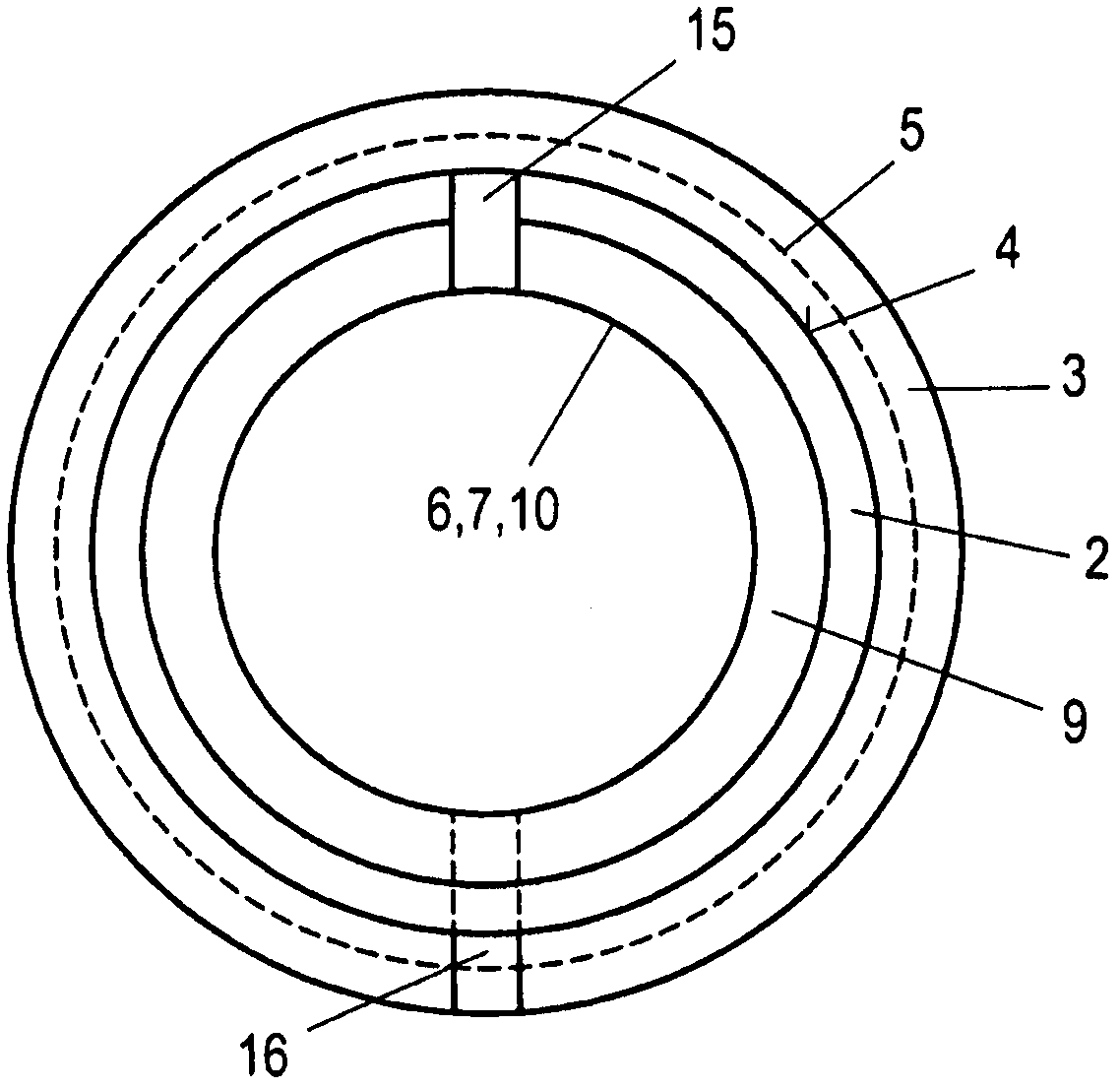
[0029] An advantageous embodiment of the oil scraping device 1 according to the invention is shown in figure 1 , 2 and 6 in. The oil scraper device 1 comprises a circumferentially divided oil scraper ring 2 and a circumferentially divided L-shaped locking ring 3 . The wiper ring 2 and the locking ring 3 are advantageously split radially at one or more points and are preferably made of one plastic, possibly also of different materials or plastics. In this case, the radial gap 15 in the circumferential direction in the wiper ring 2 and the radial gap 16 in the circumferential direction in the locking ring 3, as shown in figure 2 As shown in , they are staggered from each other along the circumferential direction (here staggered by 180°). However, the separation in the circumferential direction can be configured differently in any desired manner, for example in a tangential or locking manner. In the locking ring 3, a recess 5 for receiving a circumferential spring is provid...


PUM


Abstract

The invention relates to a wiper arrangement and compressor with such a wiper arrangement. Conventional wiper arrangements with cut rings suffer from unavoidable leakage and, in particular in an embodiment as metallic wiper ring with a sharp wiping edge, scratch on the surface of the piston rod which can be damaged in this manner. In order to eliminate these problems, a wiper arrangement with a wiper ring 2 which is split in the circumferential direction and an L-shaped cover ring 3 which is split in the circumferential direction is proposed, wherein the splitting points 16, 15 of the cover ring 3 and the wiper ring 2 are arranged offset to each other in the circumferential direction, and the wiper ring 2 is arranged abutting axially as well as radially in the recess 4 of the L-shaped cover ring 3, and the radially inner circumferential surfaces 6, 7 of the wiper ring 2 and the cover ring 3 form a common radially inner wiping surface 10.

Description

technical field [0001] The present invention relates to an oil scraping device, comprising an oil scraping ring separated in the circumferential direction and an L-shaped locking ring separated in the circumferential direction, wherein the separating point of the locking ring and the oil scraping ring is along The circumferential direction is staggered with each other, and the oil scraping ring is not only arranged in the groove of the L-shaped locking ring tightly in the axial direction but also in the radial direction; the present invention also relates to an oil scraping device with such of the compressor. Background technique [0002] In reciprocating compressors, there is usually oil in the crankcase to lubricate the moving parts of the reciprocating compressor. The oil also reaches the piston rod at the same time and is conveyed along the piston rod to the compression chamber, which is not satisfactory since this results in significant oil leakage and the oil is also ...

Claims


Application Information

Patent Timeline
Patent Type & Authority Applications(China)
IPC IPC(8): F04B39/02F04B39/00
CPCF16J15/24F16J15/26
Inventor C·霍尔德T·林德纳-西尔韦斯特M·拉格勒尔
Owner HOERBIGER KOMPRESSORTECHNIK HLDG GMBH
Why Eureka
Try Eureka