
High-transformation ratio isolated solar charging controller with MPPT function

A charge controller and solar cell technology, which is applied in current collectors, control/regulation systems, output power conversion devices, etc., can solve the problem that the solar charge controller is difficult to meet user requirements, the breakdown of the charging circuit switch tube, the switch tube Temperature rise and other problems, to avoid the breakdown accident of the switch tube and the effect of thermal damage.

Active Publication Date: 2013-04-24
EAST GRP CO LTD
View PDF4 Cites 0 Cited by
  • Summary
  • Abstract
  • Description
  • Claims
  • Application Information

AI Technical Summary

Problems solved by technology

A fatal flaw of this type of solar charge controller is that when the output voltage of the solar cell is very high and the battery voltage level configured by the user is very low, for example: when using a thin-film solar cell, the output voltage of a single thin-film solar cell can be As high as 100V, and the user configures a battery with a voltage level of 12V, there is a huge voltage difference of 80V between the input voltage and output voltage of the charge controller; when using PWM charging, the huge voltage difference of 80V is multiplied by the current It is the loss of the switch tube. It is conceivable how huge this loss is, which will cause the switch tube to heat up extremely, and the temperature of the switch tube will rise sharply, which will easily lead to the breakdown of the switch tube in the charging circuit and the occurrence of thermal damage accidents.
Therefore, under the above circumstances, conventional Buck-type solar charge controllers are difficult to meet the requirements of users

Method used


Image

  • High-transformation ratio isolated solar charging controller with MPPT function
  • High-transformation ratio isolated solar charging controller with MPPT function
  • High-transformation ratio isolated solar charging controller with MPPT function

Examples


Embodiment Construction

[0025] The present invention will be further described below in conjunction with the accompanying drawings.

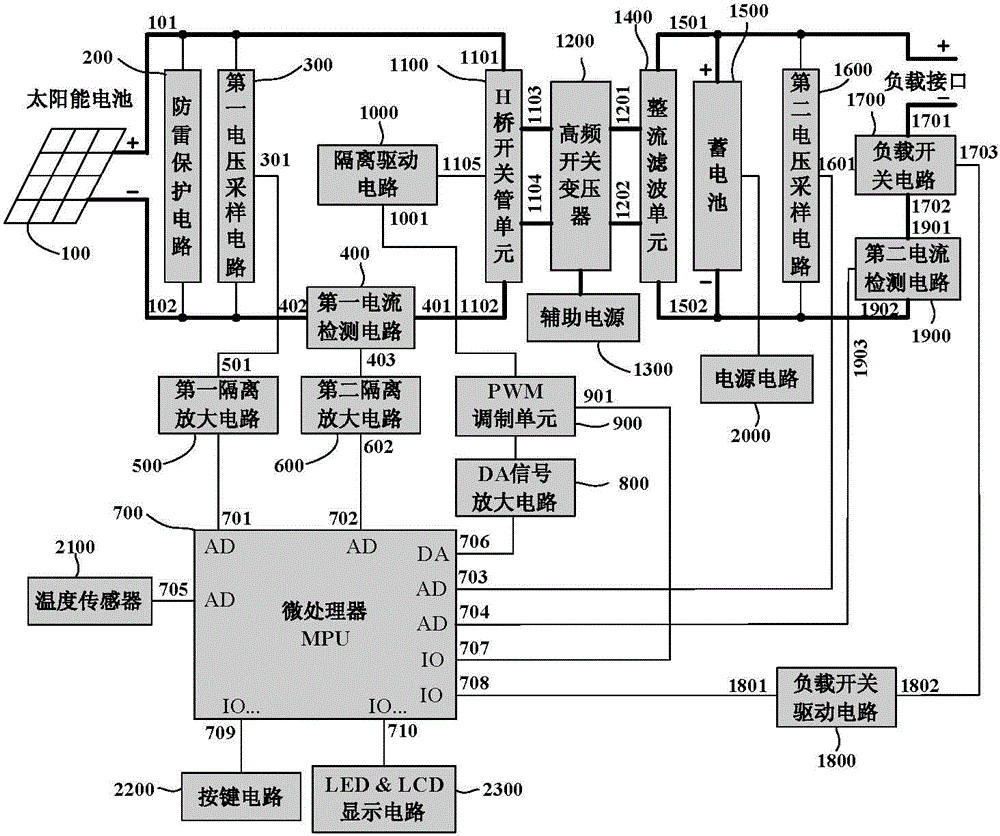
[0026] A kind of large transformation ratio isolated solar charge controller with MPPT function of the present invention, such as figure 1 As shown, it includes a microprocessor 700 (that is, MPU), a PWM modulation unit 900, a switching tube unit, and also includes a first voltage sampling circuit 300 for sampling the output voltage of the solar cell 100, and a first voltage sampling circuit 300 for sampling the output current of the solar cell 100. The first current detection circuit 400, the second voltage sampling circuit 1600 for sampling the voltage of the storage battery 1500, the isolation drive circuit 1000, and the high frequency switching transformer 1200.

[0027] The first input terminal of the first voltage sampling circuit 300 is connected to the positive output terminal 101 of the solar cell 100, the second input terminal of the first voltage sampling ci...


PUM


Abstract

The invention relates to a charging controller technology, in particular to a high-transformation ratio isolated solar charging controller with a maximum power point tracking (MPPT) function. The controller comprises a microprocessor, a pulse width modulation (PWM) unit and a switching tube unit, and also comprises a first voltage sampling circuit, a first current detection circuit, a second voltage sampling circuit, an isolation driving circuit and a high-frequency switching transformer, wherein the first voltage sampling circuit is used for sampling an output voltage of a solar battery; thefirst current detection circuit is used for sampling an output current of the solar battery; and the second voltage sampling circuit is used for sampling a voltage of a storage battery. The controller can realize dual intelligent charging control of MPPT+ system on chip (SOC); moreover, the controller can avoid a breakdown accident and a thermal damage accident of the switching tube when the output voltage of the solar battery is very high but the voltage level of the storage battery configured by a user is very low; therefore, the controller is suitable for solar power generation systems, such as an amorphous silicon membrane solar battery power generation system, with a very high solar battery output voltage and a very low storage battery voltage level.

Description

technical field [0001] The invention relates to charge controller technology, in particular to a large transformation ratio isolated solar charge controller with MPPT function. Background technique [0002] As the earth's resources become increasingly scarce and the investment cost of basic energy is rising day by day, people begin to pay more and more attention to the application and development of solar energy. Solar energy is both primary energy and renewable energy. It is rich in resources and can be used for free without transportation. It has no pollution to the environment. It has created a new form of life for human beings, enabling society and human beings to enter a state of energy conservation and reduction. The age of pollution. [0003] At present, most of the solar charge controllers are step-down charge controllers based on Buck (step-down conversion) circuit topology, which directly use the switching tube circuit to step down the output voltage of the solar ...

Claims


Application Information

Patent Timeline
Patent Type & Authority Patents(China)
IPC IPC(8): H02J7/00H02M3/335H02N6/00H02S40/38
CPCY02E10/50Y02E70/30
Inventor 韩军良徐海波汪家荣宋青华
Owner EAST GRP CO LTD
Learn More