
Static var compensation device current detection method based on transient power balance

A technology of static var compensation and current detection, applied in reactive power adjustment/elimination/compensation, reactive power/actual component measurement, measurement devices, etc., can solve problems such as flexible selection of unfavorable compensation methods, achieve good real-time performance, Effect of increasing switching frequency and reducing cost

Active Publication Date: 2011-08-17
HUAZHONG UNIV OF SCI & TECH
View PDF3 Cites 20 Cited by
  • Summary
  • Abstract
  • Description
  • Claims
  • Application Information

AI Technical Summary

Problems solved by technology

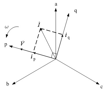
Therefore, the traditional i p -i q The reactive current detection method limits the position of the STATCOM compensation point, which is not conducive to the flexible selection of compensation methods

Method used


Image

  • Static var compensation device current detection method based on transient power balance
  • Static var compensation device current detection method based on transient power balance
  • Static var compensation device current detection method based on transient power balance

Examples


Embodiment Construction

[0030] In the present invention, the three-phase current at the low-voltage side of the transformer is first transformed from the abc three-phase coordinate system to the pq rotating coordinate system according to the direction of the phase voltage rotation vector at the low-voltage side of the transformer, referred to as abc / pq coordinate transformation, to obtain the reactive DC component i of the load current qL ; Then according to the principle of power balance, i qL Injected reactive current DC component i required to convert to STATCOM compensation point qT , as the q-axis DC component i of the STATCOM output reference current qref ; then i qref According to the direction of the phase voltage rotation vector of the STATCOM compensation point, the abc / pq coordinate inverse transformation is performed to obtain the command value of the three-phase output reactive current of the STATCOM. Controlling the output current of the STATCOM in this way can ensure that the reactiv...


PUM


Abstract

The invention provides a static var compensation device current detection method based on transient power balance. The static var compensation device current detection method specifically comprises the following steps of: performing phase locking on the phase voltage of an A phase on the low voltage side of a transformer and the phase voltage of the A phase at a compensation point of a static var compensator (STATCOM); performing abc / pq transformation on the three-phase current n the low voltage side of the transformer according to a direction of a rotation vector of the phase voltage on the low voltage side of the transformer to obtain a reactive DC component of load current; converting the reactive DC component of the load current into a reactive current DC component required to be injected into the compensation point of the STATCOM as a q-axis DC component iqref of the output reference current of the STATCOM according to a transient power balance principle; and performing abc / pq inverse transformation on the iqref according to the direction of the rotation vector of the phase voltage at the compensation point of the STATCOM to obtain a three-phase output reactive current directive value of the STATCOM to control the actual output current of the STATCOM. By the method, the problems of current detection caused by the transformer crossing of the compensation point of the STATCOM and a load current detection point are solved, the STATCOM can be flexibly arranged at any position, and simultaneously, a reactive current detection algorithm is quick in response.

Description

technical field [0001] The invention relates to a reactive power compensation technology of a power system, in particular to a current detection method of a static reactive power compensation device. Background technique [0002] In the power system, in order to improve the power quality of the grid and increase the power factor of the power supply side of the grid, a reactive power compensation device is usually installed on the low-voltage side of the transformer. Static var compensator (Static var compensator, hereinafter referred to as STATCOM) is a widely used dynamic var compensation device. During STATCOM operation, when the reactive power required by the load changes, STATCOM is required to quickly perform dynamic tracking compensation, which firstly relies on the real-time detection and calculation method of STATCOM command current. [0003] At present, the calculation method of STATCOM command current detection widely adopts i p -i q Operation method. i p -i ...

Claims


Application Information

Patent Timeline
IPC IPC(8): H02J3/18G01R19/00G01R19/06
CPCY02E40/16Y02E40/12Y02E40/10
Inventor 尹项根文明浩张哲王存平刘健熊卿张斌
Owner HUAZHONG UNIV OF SCI & TECH
Learn More