LED (light emitting diode) fluorescent lamp and fluorescent lamp connecting circuit

A technology of LED fluorescent lamps and LED lamp groups, which is applied in the direction of electric lamp circuit layout, circuit layout, light source, etc., can solve the problems of wasting resources and increasing costs, and achieves the effect of good adjustment

Inactive Publication Date: 2011-08-17
刘昌贵
View PDF8 Cites 4 Cited by
  • Summary
  • Abstract
  • Description
  • Claims
  • Application Information

AI Technical Summary

Problems solved by technology

[0011] Since fluorescent lamps have been widely used in daily life, brackets, lamp panels and peripheral circuits specially designed for fluorescent lamps have already been deployed in large quantities. If the peripheral circuits of fluorescent lamps that have been formed are changed in order to use LED fluorescent lamps, it will increase a lot of cost. , and waste a lot of resources

Method used


Image

  • LED (light emitting diode) fluorescent lamp and fluorescent lamp connecting circuit
  • LED (light emitting diode) fluorescent lamp and fluorescent lamp connecting circuit
  • LED (light emitting diode) fluorescent lamp and fluorescent lamp connecting circuit

Examples


Embodiment Construction

[0081] The following will clearly and completely describe the technical solutions in the embodiments of the present invention with reference to the drawings in the embodiments of the present invention.

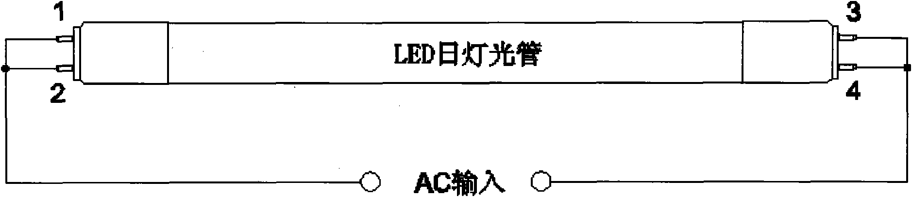
[0082] An LED fluorescent lamp provided by the present invention includes an LED fluorescent tube, the LED fluorescent tube includes a first end cover and a second end cover, and the first end cover and the second end cover respectively include two pins, Inside the LED fluorescent tube, a first bridge rectifier circuit is connected in parallel between the two pins of the first end cap and a second bridge is connected in parallel between the two pins of the second end cap type rectifier circuit, the output terminals of the first bridge rectifier circuit and the second bridge rectifier circuit are connected in parallel with LED lamp groups, and the LED lamp groups include LED light source groups and are used to provide constant current to the LED light source groups Or a constan...


PUM


Abstract

The embodiment of the invention discloses an LED (light emitting diode) fluorescent lamp and a fluorescent lamp connecting circuit, The LED fluorescent lamp comprises an LED fluorescent lamp tube which comprises a first end cover and a second end cover, the first end cover and the second end cover respectively comprise two pins, a first bridge rectifier circuit and a second bridge rectifier circuit are respectively connected in parallel between the pins of the first end cover and the second end cover, the output ends of the first bridge rectifier circuit and the second bridge rectifier circuit are connected in parallel with an LED lamp bank which comprises an LED light source group and a circuit which is used for providing constant current or constant voltage for the LED light source group, a first capacitor is connected in series between the input end of the LED lamp bank and a pin of the second end cover, and a second capacitor is connected in series between the output end of the LED lamp group and a pin of the first end cover. By adopting the LED fluorescent lamp and the fluorescent lamp connecting circuit, a fluorescent lamp is directly replaced by the LED fluorescent lamp under the condition that a peripheral circuit of a traditional fluorescent lamp is not changed.

Description

technical field [0001] The invention relates to the LED field, in particular to an LED fluorescent lamp and a fluorescent lamp connection circuit. Background technique [0002] Among traditional lighting sources, straight tube fluorescent lamps and circular fluorescent lamps have been widely used in commercial lighting, office lighting and home lighting. like figure 1 and figure 2 Shown are the circuit diagrams of two common fluorescent lamps at present. like figure 1 As shown, the first common fluorescent lamp circuit includes an inductive ballast, a fluorescent tube and a starter S installed on the starter base Y, and the mains (that is, commonly referred to as alternating current) is energized from the inductive ballast One end of the device and one end of the fluorescent lamp are input at the same time. like figure 2 As shown, the second common fluorescent lamp circuit replaces the magnetic ballast in the first way with an electronic ballast. [0003] In terms o...

Claims


Application Information

Patent Timeline
IPC IPC(8): F21S2/00F21V23/02F21V23/04F21V23/06H05B37/02F21Y101/02F21K9/278F21Y115/10
Inventor 刘昌贵
Owner 刘昌贵
Why Eureka
Try Eureka