
Multi-control-unit multi-beam laser perforation device in oil well

A technology with multiple control units and control units, applied in optics, installation, optical components, etc., can solve the problems of low perforation efficiency, influence, laser influence, etc., and achieve the effect of improving work efficiency

Inactive Publication Date: 2011-08-17
NORTHWEST UNIV(CN)
View PDF9 Cites 4 Cited by
  • Summary
  • Abstract
  • Description
  • Claims
  • Application Information

AI Technical Summary

Problems solved by technology

At present, bullets and shaped explosives are commonly used to perforate oil wells, but these methods have shallow perforation depths, uncontrollable perforation directions, and will have a compaction effect on the formation, resulting in a decrease in the permeability of the formation
These problems have always affected the perforation and completion operations of oil wells, limiting the increase in oil well productivity
However, there is only one set of optical elements to control the laser in this device, and the perforation efficiency is not high
In addition, when the device is used for perforating operations, the complex environment downhole and the sundries generated during perforating will affect the laser, reducing the efficiency of laser perforating operations

Method used


Image

  • Multi-control-unit multi-beam laser perforation device in oil well
  • Multi-control-unit multi-beam laser perforation device in oil well
  • Multi-control-unit multi-beam laser perforation device in oil well

Examples


Embodiment

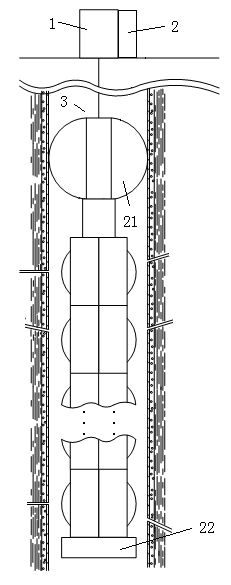
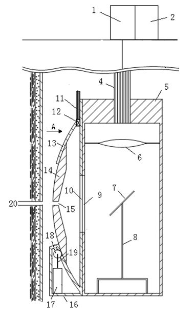
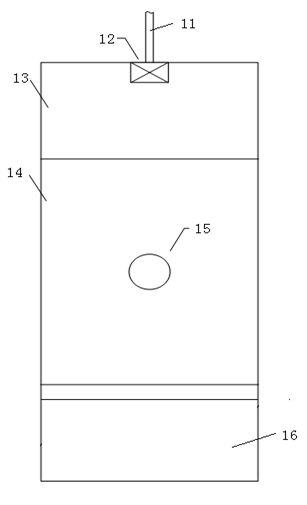
[0056] refer to Figure 1 to Figure 3 And as Figure 4 As shown, the device in this embodiment includes a laser source 1, a high-pressure gas source 2, and a downhole laser perforator 3. The laser source 1 and the high-pressure gas source 2 are located on the ground, so that on the one hand, the influence of the complex environment downhole on the instrument is avoided. On the other hand, it eliminates the limitation of the size of the well pipe on the size and volume of the instrument; the laser source 1 is a high-power all-solid-state laser, and the high-energy laser generated by it is transmitted to the downhole laser perforator 3 through an optical fiber; where:

[0057] The downhole laser perforator 3 includes a centralizer 21, a rotary controller 22 and three groups of laser perforation units, wherein the three groups of perforation units are connected in sequence along the longitudinal direction, and the centralizer 21 is installed on the top of the downhole laser perfo...


PUM


Abstract

The invention belongs to the field of well completion technology of oil wells, and particularly relates to a multi-control-unit multi-beam laser perforation device in an oil well. The device mainly comprises a laser source, a high-pressure gas source and an underground laser perforator, wherein the laser source generates high-energy laser; the underground laser perforator comprises multiple laserperforation devices which are arranged orderly, controls the high-energy laser to perform the perforation operation in the oil well and controls to eject the gas output by the high-pressure gas source along the emergent direction of the laser so as to provide a clean channel for the laser perforation. The device provided by the invention controls multiple beams of high-energy laser to perform theperforation operation in the oil well at the same time, realizes high perforation efficiency, deep perforation and flexible and controllable perforation direction, improves the formation permeabilityand obviously increases the oil well capacity.

Description

technical field [0001] The invention belongs to the technical field of oil well completion, and in particular relates to a multi-control-unit multi-beam laser perforation device for downhole oil wells. Background technique [0002] Petroleum downhole perforation technology belongs to a kind of oil well completion technology, specifically refers to opening the well pipe, cement layer and formation, and establishing the flow channel between the formation and the well pipe. At present, bullets and shaped explosives are commonly used to perforate oil wells, but these methods have shallow perforation depths, uncontrollable perforation directions, and have a compaction effect on the formation, resulting in a decrease in the permeability of the formation. These problems have always affected the perforating and completion operations of oil wells, limiting the improvement of oil well productivity. The use of high-power lasers to carry out oil well perforation operations can effectiv...

Claims


Application Information

Patent Timeline
Patent Type & Authority Applications(China)
IPC IPC(8): E21B43/11E21B43/119E21B21/16G02B7/198G02B1/11G02B1/10
Inventor 白晋涛张云博陈浩伟许冠军陆宝乐任兆玉
Owner NORTHWEST UNIV(CN)
Learn More