
Yarn tensioner

A technology of tensioner and yarn, applied in the direction of thin material processing, textile and paper making, loom, etc., can solve problems such as difficulties, and achieve the effect of less risk of yarn breakage

Active Publication Date: 2013-01-09
范德威尔(中国)纺织机械有限公司
View PDF7 Cites 0 Cited by
  • Summary
  • Abstract
  • Description
  • Claims
  • Application Information

AI Technical Summary

Problems solved by technology

However, setting and gradually varying high yarn tension is a difficult task for this type of yarn tensioner

Method used


Image

  • Yarn tensioner
  • Yarn tensioner
  • Yarn tensioner

Examples


Embodiment Construction

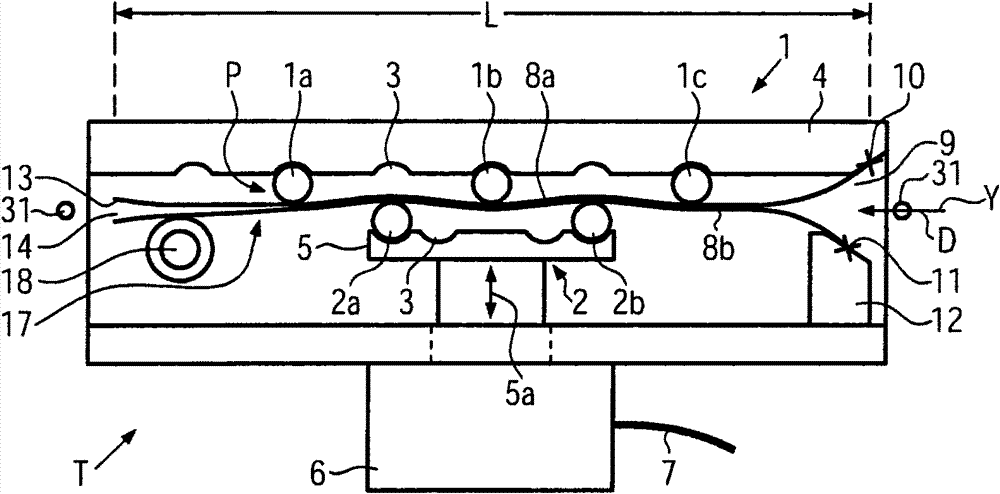
[0035] figure 1 An embodiment of a yarn tensioner T is schematically shown, especially designed to handle heavy yarn qualities. The yarn tensioner T is a so-called heavy-duty yarn tensioner, used e.g. Speed ​​operation, i.e. yarn tensioners for applications where the advancing yarn requires a relatively high yarn tension even in the event of unavoidable knots, tangles or irregular passages of the yarn The situation with the yarn tensioner T remains relatively constant as set and allows for example knots to pass smoothly without severe tension peaks without the risk of yarn breakage and the set yarn The thread tension does not change much through the passage of the knot and is quickly regained after the passage of the knot.

[0036] exist figure 1 The yarn tensioner T in is a combination of a deflection tensioner and a clamping or blade tensioner and comprises a series of deflection elements on both sides of the yarn path P of the yarn traveling in the yarn travel direction ...


PUM


Abstract

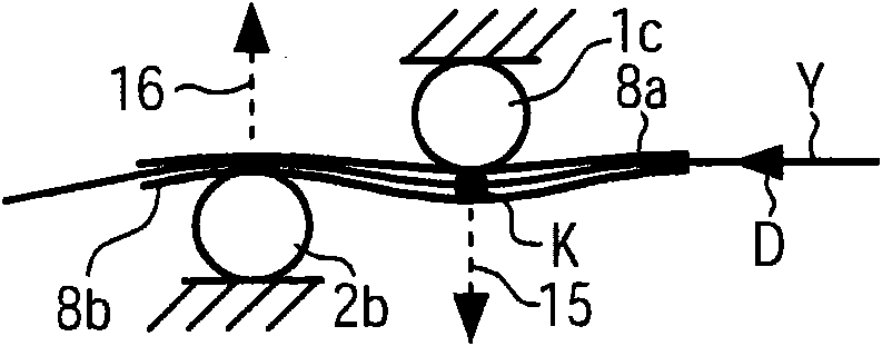
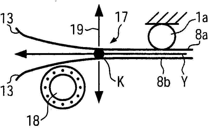
In a yarn tensioner T comprising a series of rigid yarn deflecting elements 1 commonly defining a yarn path P, the yarn deflecting elements being distributed with interspaces in-between on both opposite sides of the yarn path such that a respective yarn deflecting element is located at one side with an offset in yarn run direction D relative to a yarn deflecting element 1 located at the opposite side, at least one yarn deflecting element 2a, 2b being adjustable substantially perpendicularly to the yarn path in order to vary the tensioning effect in an operative condition of the yarn tensioner, the yarn path P is lined between the yarn deflecting elements 1, 2 by at least one thin walled flexible spring leaf 8a, 8b per side of the yarn path P, the spring leaves being biased towards each other by the deflecting elements, such that one respective spring leaf 8a, 8b is supported at one location of the yarn path P at a deflecting element while the other respective and parallelly arranged spring leaf is free at the same location of yield perpendicularly to the yarn run direction D away from the one spring leaf, the spring leaf 8a, 8b being markedly longer in yarn run direction D than the distance occupied by the series of yarn deflecting elements 1, 2 with the longitudinal free end of the spring leaves being distant in yarn run direction from the respective first yarn deflecting element.

Description

technical field [0001] The invention relates to a thread tensioner according to the preamble of claim 1 . Background technique [0002] In the yarn tensioner known from US 5738295A the yarn path is determined by four fixed rigid deflection elements on one side of the yarn path and three rigid deflection elements on the other side of the yarn path , so that the yarn path has a zigzag structure. The three deflection elements on the other side of the yarn path are generally adjustable perpendicular to the direction of yarn travel in order to vary the tensioning effect by changing the deflection angle around the deflection elements. The advancing yarn is only braked by friction, depending on the overall deflection angle and the coefficient of friction between the yarn and the deflection element. A yarn tensioner has to create a tension in the yarn which can be precisely adjusted and which will remain relatively constant at the set value. However, whenever the traveling yarn c...

Claims


Application Information

Patent Timeline
Patent Type & Authority Patents(China)
IPC IPC(8): B65H59/26
CPCB65H59/30B65H59/24B65H2701/31D03D47/34
Inventor 比约恩·哈尔瓦松安德斯·斯万斯特伦
Owner 范德威尔(中国)纺织机械有限公司
Learn More