
Flyback integrated magnetic converter used for multi-circuit LED (light-emitting diode) driving

A technology of LED driver and converter, applied in the direction of electric lamp circuit layout, lighting device, light source, etc., can solve the problems of large loss, influence of current sharing accuracy magnification and so on

Inactive Publication Date: 2011-08-10
FUZHOU UNIV
View PDF4 Cites 4 Cited by
  • Summary
  • Abstract
  • Description
  • Claims
  • Application Information

AI Technical Summary

Problems solved by technology

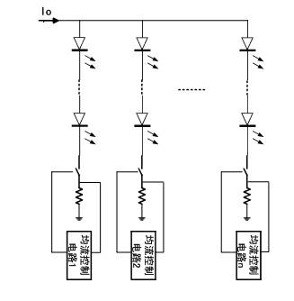
The greater the resistance value of the current sharing resistor, the higher the current sharing accuracy, but the greater the loss; Patent Document 1 (CN101715267A) respectively connects a triode and a resistor with a small resistance in series in two LED branches, through comparison A simple feedback network is used to achieve current sharing of two LEDs. Its disadvantages are: the accuracy of current sharing will be affected by the consistency of the magnification of the two triodes in the feedback network; and it is only suitable for current sharing of two LEDs; Patent Document 2 (CN101702849A) also proposes a multi-channel PWM chopper current sharing circuit, such as figure 1 shown
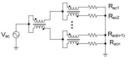
But this circuit requires the addition of additional current sharing transformer magnetics

Method used


Image

  • Flyback integrated magnetic converter used for multi-circuit LED (light-emitting diode) driving
  • Flyback integrated magnetic converter used for multi-circuit LED (light-emitting diode) driving
  • Flyback integrated magnetic converter used for multi-circuit LED (light-emitting diode) driving

Examples


Embodiment Construction

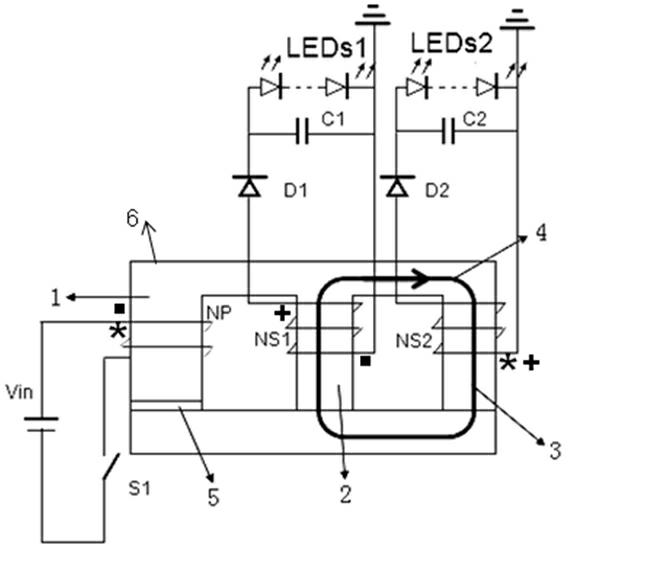
[0015] Solution 1 of the present invention is to provide a flyback magnetic integrated converter that can be used to drive multiple LEDs, including a DC power supply, a primary switch tube, a magnetic core, a primary winding, at least two secondary windings, and corresponding secondary windings. The side rectifier circuit and the LED string load are characterized in that: the magnetic core has at least three magnetic columns, one of which has an air gap to form the excitation inductance energy storage magnetic circuit of the converter, and the other magnetic columns are not provided with air gaps. gap; the primary winding is wound on the magnetic column with an air gap, and the secondary winding is wound on the magnetic column without an air gap in a one-to-one correspondence, and the primary winding passes through the primary The side switch is connected with the DC power supply; the secondary windings are respectively connected with the LED load through a rectification and fi...


PUM


Abstract

The invention relates to a flyback integrated magnetic converter used for multi-circuit LEDs (light-emitting diode), which comprises a direct current power supply, a primary switch tube, a magnetic core, a primary winding, at least two secondary windings as well as a corresponding primary rectifier circuit and a corresponding LED string load. The flyback integrated magnetic converter is characterized in that the magnetic core is provided with at least three magnetic columns, wherein one magnetic column is provided with an air gap; and the rest magnetic columns are not provided with air gaps; the primary winding is twisted on the magnetic column provided with the air gap; the secondary windings are correspondingly twisted on the magnetic columns without air gaps one by one; the primary winding is connected with the direct current power through a primary switch; the secondary windings are respectively connected with the LED load through a rectifier filter circuit. As a low-magnetic drag magnetic loop formed by a material with high magnetic conductivity is not provided with an air gap and is formed in every two secondary windings, the flyback integrated magnetic converter can automatically distribute or equalize the current between a plurality of independent loads according to a certain proportion without a complex control system, so that the flyback integrated magnetic converter has low cost and simple structure, can be used for LED driving, and control the load current of multi-circuit LEDs.

Description

technical field [0001] The invention relates to a flyback magnetic integrated converter which can be used for multi-channel LED driving. Background technique [0002] LED is known as the third-generation lighting technology, which has the advantages of energy saving, environmental protection, and long life. Due to the electrical characteristics of the LED, a small voltage change can cause a large current change, and the change in the current will cause a change in the luminance of the LED. Therefore, when used as a surface light source, or when the LED lighting device is composed of multiple LED units , in order to ensure the uniformity of light emission, it is necessary to ensure that the current on each LED is nearly equal. [0003] One of the most common current sharing methods is to connect resistors in series with each LED, and use the resistor voltage drop to help achieve current sharing. The greater the resistance value of the current sharing resistor, the higher th...

Claims


Application Information

Patent Timeline
Patent Type & Authority Applications(China)
IPC IPC(8): H05B37/02
Inventor 陈为王小博黄国泰
Owner FUZHOU UNIV
Learn More