Method for receiving and sending mobile equipment signal
A technology for signal transmission and reception and mobile equipment, applied in the field of signal transmission and reception of mobile equipment, to achieve the effect of improving performance
- Summary
- Abstract
- Description
- Claims
- Application Information
AI Technical Summary
Problems solved by technology
Method used
Image
Examples
specific Embodiment 1
[0065] The implementation scenario of this preferred embodiment is that the UE is located at the edge of a cell in an N-frequency network, and there are two cells, CELL 1 and CELL 2, within the receiving range of the UE.
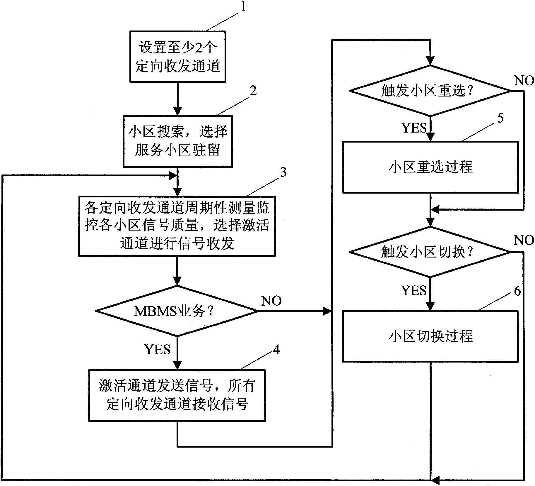
[0066] The overall process of this embodiment is attached figure 1 Shown:
[0067] 1. The UE sets at least two directional transceiving channels covering different spatial ranges, and the directional transceiving channels together cover the omnidirectional transceiving spatial range of the mobile device;
[0068] In this embodiment, the number of directional transceiver channels is 3, corresponding to the channel numbers 1, 2, and 3, and the space ratios occupied in omnidirectional coverage are 1 / 2, 1 / 4, and 1 / 4 respectively;
[0069] 2. The mobile device performs cell search based on all directional transceiver channels, and selects a serving cell to reside in;
[0070] This step further includes:
[0071] 201. Each directional channel receives the signa...
specific Embodiment 2
[0131] The implementation scenario of this preferred embodiment is that the UE is in the BBU+RRU high-speed railway coverage scenario (train moving speed 450km / h), and the two RRUs of the BBU belonging to the same cell CELL 1 cover the edge overlapping area.
[0132] The overall process of this embodiment is attached figure 1 Shown:
[0133] Steps 1~2 are identical with specific embodiment 1;
[0134] In this embodiment, the number of directional transceiver channels is set to 2, and the corresponding channel numbers are 1, 2, and the space ratios occupied in the omnidirectional coverage are 1 / 2, 1 / 2 respectively;
[0135] In this embodiment, after step 2, select CELL 1 to reside in as the serving cell;
[0136] 3. Taking the preset channel selection time as the cycle, each directional transceiver channel independently measures and monitors the signal quality of the candidate cells in the list of all neighboring cells; selects at least one directional transceiver channel wit...
specific Embodiment 3
[0163] The implementation scenario of this preferred embodiment is that the UE is in a BBU+RRU high-speed railway coverage scenario (train moving speed 450km / h), and two RRUs of BBUs belonging to two different cells CELL 1 and CELL 2 respectively belong to two different cells. overlapping area.
[0164] The overall process of this embodiment is attached figure 1 Shown:
[0165] Steps 1 and 2 are identical to the specific embodiment 2;
[0166] Wherein, after step 2, CELL 1 is selected as the serving cell to reside in;
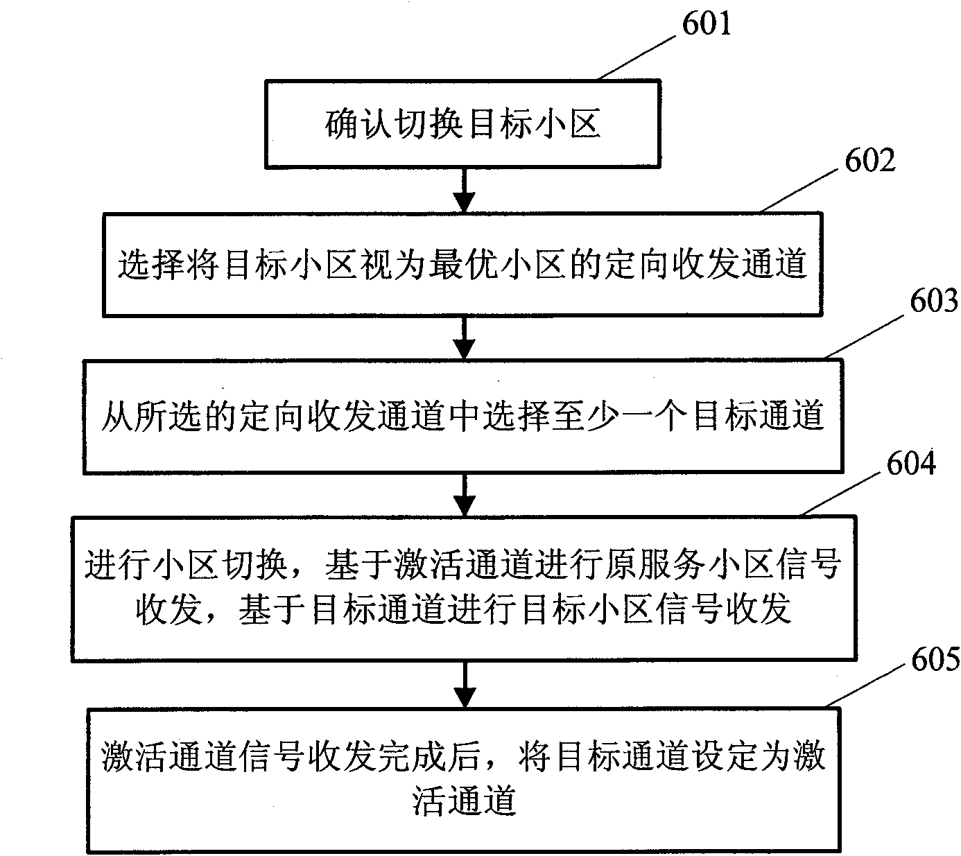
[0167] 3. Taking the preset channel selection time as the cycle, each directional transceiver channel independently measures and monitors the signal quality of the candidate cells in the list of all neighboring cells; selects at least one directional transceiver channel with the best signal quality for receiving the serving cell as the active channel, based on Activate the channel to send and receive signals; the specific process of this step is attached F...
PUM
 Abstract
Description
Claims
Application Information
 - R&D
- Intellectual Property
- Life Sciences
- Materials
- Tech Scout
- Unparalleled Data Quality
- Higher Quality Content
- 60% Fewer Hallucinations
Browse by: Latest US Patents, China's latest patents, Technical Efficacy Thesaurus, Application Domain, Technology Topic, Popular Technical Reports.
© 2025 PatSnap. All rights reserved.Legal|Privacy policy|Modern Slavery Act Transparency Statement|Sitemap|About US| Contact US: help@patsnap.com


