
Cracking furnace for producing ethylene by cracking hydrocarbon steam

A technology of cracking ethylene and cracking furnace, which is applied in the field of petrochemical industry. It can solve the problems of furnace tube bending, poor flexibility of large-diameter bent tubes, and movement with the second-pass tube, so as to achieve the force balance of the furnace tube and prolong the service life. Effect

Active Publication Date: 2011-08-10
CHINA PETROLEUM & CHEM CORP +1
View PDF6 Cites 16 Cited by
  • Summary
  • Abstract
  • Description
  • Claims
  • Application Information

AI Technical Summary

Problems solved by technology

[0011] The 1-1 type (U-shaped) furnace tube has a large specific surface area, can match with the linear quenching boiler, and has good mechanical properties, but the operation cycle is slightly worse than other two-pass furnace tubes
[0012] The 2-1 type furnace tube has a large specific surface area and can match the linear quenching boiler. However, compared with the 1-1 type (U-shaped) furnace tube, the first-pass tube needs to be combined into one by a Y-shaped piece. The root pipe, the two pipes will be deviated during manufacture and operation, the diameter of the merged furnace pipe is larger, and the flexibility of the large-diameter bend is worse than that of the small bend
With this kind of structure, since there are multiple first-pass tubes and one second-pass tube, when the furnace tube is heated and expanded, the second-pass tube expands downward first, and the first-pass tube is pulled downward by the second-pass tube. Downward movement, where the force farther away from the second-pass tube is smaller, and the force near the second-pass tube is larger. In addition, the lower collecting tube is rigidly connected, and the expansion difference between the second-pass tube and the first-pass tube It can only be adjusted by the balance system installed at the inlet of the first pass tube. As a result, when the first pass tube cannot move with the second pass tube, it will cause the furnace tube to bend

Method used


Image

  • Cracking furnace for producing ethylene by cracking hydrocarbon steam
  • Cracking furnace for producing ethylene by cracking hydrocarbon steam
  • Cracking furnace for producing ethylene by cracking hydrocarbon steam

Examples


Embodiment 1

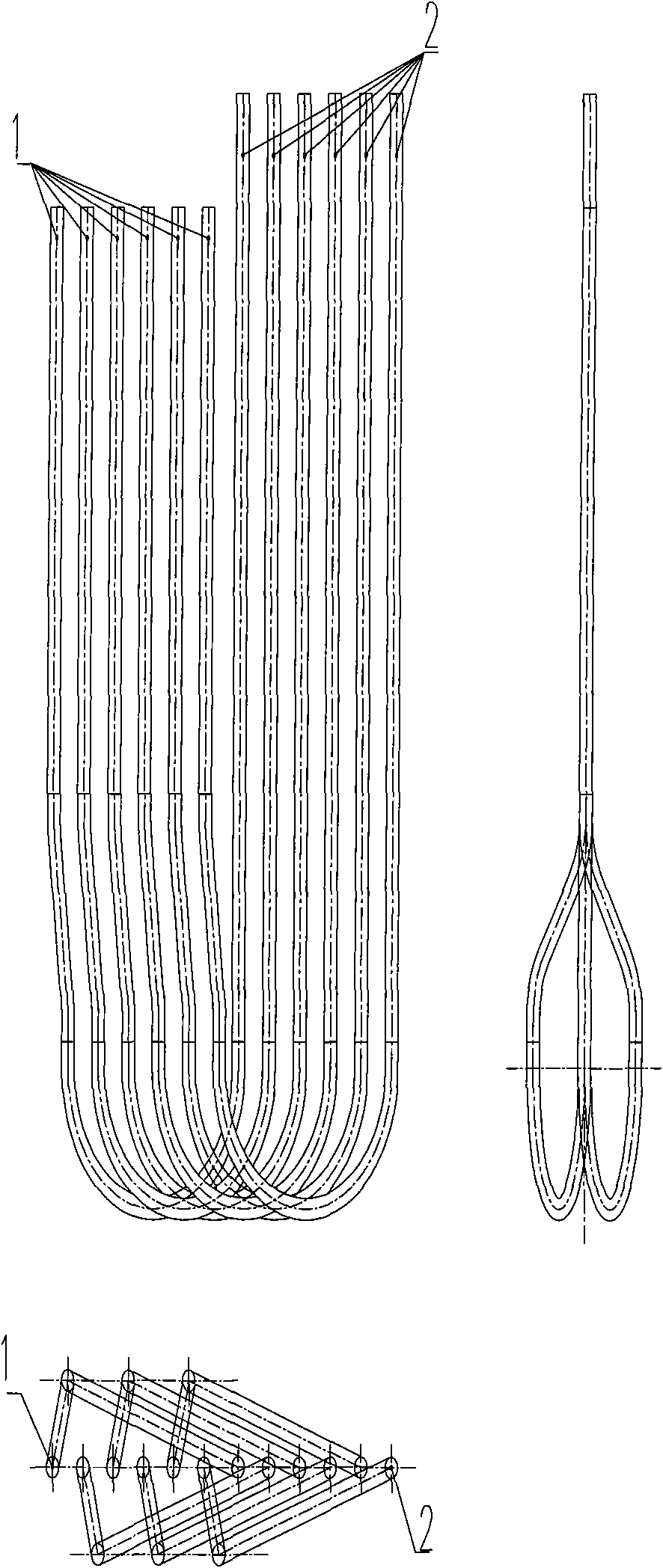
[0055] Such as Figure 4A and Figure 4B As shown, two-pass 2-1 type branch variable-diameter furnace tubes are used, in which the first-pass furnace tubes are arranged on both sides of the second-pass furnace tubes, the number of second-pass furnace tubes is 8, and the total number of first-pass furnace tubes is There are 16 tubes, and 8 tubes are arranged on both sides of the second-pass tube.

[0056] The furnace tubes of the first pass and the second pass are in the same plane. The two same symmetrical bent pipes of the connecting piece between the first and second pass furnace tubes of each radiant furnace tube are in the same plane and form an included angle with the furnace tube plane. A set of symmetrical bent tubes of radiant furnace tubes is projected as a set of parallel lines in top view. There is an S-bend at the first tube on both sides of the second tube and bends out of the furnace tube plane. The angle between the top view projection and the furnace tube pl...

Embodiment 2

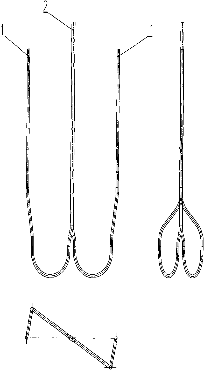
[0058] Such as Figure 5 As shown, the 2-1 type two-pass branch variable-diameter furnace tube is used, in which the first-pass furnace tube is arranged on both sides of the second-pass furnace tube, the number of second-pass furnace tubes is 8, and the total number of first-pass furnace tubes is There are 16 tubes, and 8 tubes are arranged on both sides of the second-pass tube.

[0059] The second-pass furnace tube is in a vertical plane, and the two planes where the first-pass furnace tube is located form an identical angle with the plane where the second-pass furnace tube is located and take it as a plane of symmetry. The two identical symmetrical bent pipes of the connecting piece between the first and second pass tubes of each radiant furnace tube are in the same plane and form an included angle with the plane of the second pass furnace tube. A set of symmetrical bent tubes of radiant furnace tubes is projected as a set of parallel lines in top view. The first-pass tube...

Embodiment 3

[0062] Such as Figure 6 As shown, two-pass 2-1 type branch variable-diameter furnace tubes are used, in which the first-pass furnace tube is arranged on one side of the second-pass furnace tube, the number of second-pass furnace tubes is 8, and the total number of first-pass furnace tubes is For 16.

[0063] The furnace tubes of the first pass and the second pass are in the same plane. The two planes where the two identical symmetrical bends of the connecting piece between the first and second pass furnace tubes of each radiant furnace tube are located form the same angle with the plane of the second pass furnace tube and take it as a plane of symmetry. The included angle depends on the specific furnace The number of pipes, pipe diameter and arrangement of pipe rows are determined. The first pass tube has two S-bent tubes that bend out of the furnace tube plane respectively, and the angle between the top view projection and the furnace tube plane is determined according to ...


PUM


Abstract

The invention discloses a cracking furnace for producing ethylene by cracking hydrocarbon steam. The cracking furnace is characterized in that a radiant coil is a two-stage branched and diameter-altered radiant tube; a plurality of first-stage tubes are combined into one tube in an inverted Y-shaped tube form at the lower end of the second-stage tube; and the first-stage tubes are connected with the second-stage tube through a three-dimensional structural connector formed by symmetric curved tubes and S-shaped curved tubes. The invention has the following beneficial effects: the mechanical property defects of a 2-1 type branched tube, a 4-1 type branched tube and the like are overcome; and the technological properties can be improved, and the service life of the radiant coil and the operational cycle of the cracking furnace can be prolonged finally.

Description

technical field [0001] The invention belongs to the field of petrochemical industry, and in particular relates to a radiation furnace tube structure of an ethylene cracking furnace in petrochemical production. Background technique [0002] The ethylene cracking technologies used in petrochemical ethylene units are mainly American LUMMUS, Stone & Webster, Kellog & Braun Root, European German Linde, Technip (KTI) and domestically developed CBL cracking furnaces. Their techniques are as follows: [0003] LUMMUS company in the United States: use 4-1, 5-1, 6-1 and other two-pass furnace tubes, usually four small groups of furnace tubes are equipped with a quenching (waste heat) boiler; [0004] Stone&Webster Company of the United States: U-shaped furnace tubes are used, usually a small or two small groups of furnace tubes are equipped with a linear quenching (waste heat) boiler, and all bottom heating is provided; [0005] Kellog & Braun Root Company in the United States: U-sha...

Claims


Application Information

Patent Timeline
Patent Type & Authority Applications(China)
IPC IPC(8): C07C11/04C07C4/04
Inventor 何细藕刘敬坤李昌力申海女郭玉萍邵晨
Owner CHINA PETROLEUM & CHEM CORP
Learn More