Combined type circular pipe pipe-fin heat exchanger

A heat exchanger, combined technology, applied in the direction of tubular elements, heat exchange equipment, lighting and heating equipment, etc., can solve the problem of large resistance loss, improve heat exchange performance, reduce flow resistance loss, reduce size Effect

Active Publication Date: 2011-08-03
LANZHOU JIAOTONG UNIV
View PDF6 Cites 5 Cited by
  • Summary
  • Abstract
  • Description
  • Claims
  • Application Information

AI Technical Summary

Problems solved by technology

However, the area with poor heat transfer capacity on the surface of the fin is the area in contact with the wake area of ​​the circular tube. The flow linearity of the fluid flowing through the circular tube is worse than that of the flat tube, that is, the fluid flows through the front end of the circular tube. Large resistance loss near the stagnation point and when flowing through the wake area of ​​the circular tube

Method used


Image

  • Combined type circular pipe pipe-fin heat exchanger
  • Combined type circular pipe pipe-fin heat exchanger
  • Combined type circular pipe pipe-fin heat exchanger

Examples


Embodiment Construction

[0014] Below in conjunction with accompanying drawing, the present invention is described in further detail:

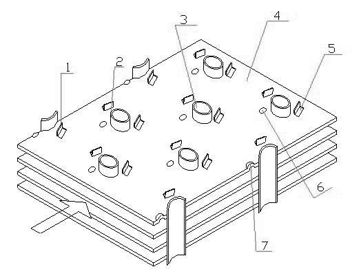
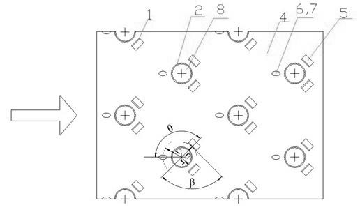
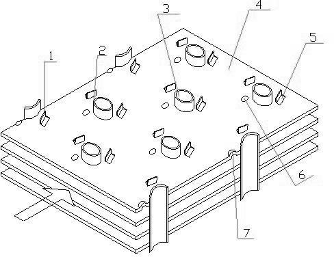
[0015] The invention is a round tube fin heat exchanger, which comprises round tubes 3 arranged along the gas flow direction and fins 4 sleeved on the round tubes 3 . In order to improve the heat exchange performance, the round tubes 3 are arranged in a fork row, and the holes 8 for fitting the round tubes 3 are arranged on the fins 4, and a pair of rectangular winglet planar vortex generators 1 are punched out at the rear of each hole 8. And perpendicular to the fin 4 , a pair of rectangular small holes 8 are left on the fin 4 . The side where the vortex generator 1 is connected to the fin 4 is the bottom side. The length of the base of the vortex generator 1 is 0.3-0.5 of the radius of the hole 8, and the height is 0.6-0.85 times of the radius of the hole 8. An elliptical convex hull 6 is punched out at the front of the hole 8 , the long axis direction of the oval...


PUM


Abstract

The invention discloses a combined type circular pipe pipe-fin heat exchanger, relating to the technical field of heat exchangers. The combined type circular pipe pipe-fin heat exchanger comprises circular pipes arranged along a flow direction of gas and fins sleeved on the circular pipes, wherein the fins are provided with holes used for being sleeved with the circular pipes, a flanging boss is arranged on the edge of each hole, a pair of rectangular small wing plane vortex generators is punched at the rear part of each hole, and an oval convex hull is punched at the front part of the hole. The oval convex hulls have better streamline, and when flowing through the oval convex hulls, a fluid changes a flow direction and flows along the convex hulls, thereby the loss of flow resistance caused by directly and vertically washing the circular pipes with the fluid is reduced. Meanwhile, after the fluid flows through the rectangular vortex generators, secondary flow following a mainstream is generated in the fluid. When a part of the fluid flows through the vortex generators, a fluid channel is formed between each circular pipe and each vortex generator and is led to a recirculation region of the circular pipes, thereby the size of the recirculation region at the downstream of the circular pipes is reduced, the heat exchanging performance between the pipe wall at the downstream of the circular pipes as well as the surface of adjacent fins and the fluid is improved, and the consumption of the mechanical energy in the recirculation region is reduced.

Description

technical field [0001] The invention relates to the technical field of heat exchangers, in particular to a combined circular tube-tube-fin heat exchanger. Background technique [0002] Since the round tube fin heat exchanger has a wide range of uses, it is very important to enhance the heat transfer of the round tube fin heat exchanger. Researchers are committed to enhancing the heat transfer capacity of the tube-fin heat exchanger while reducing the increase in resistance loss as much as possible, that is, reducing the operating cost of the tube-fin heat exchanger. Fins are usually installed on the outside of the tube to increase the heat transfer area and reduce thermal resistance, but the area of ​​the fins cannot be increased indefinitely due to the limitation of economy and fin efficiency. In order to further improve the heat transfer performance of the round tube fin heat exchanger, the fin surface is made into various structures. The vortex generator punched out on ...

Claims


Application Information

Patent Timeline
Patent Type & Authority Applications(China)
IPC IPC(8): F28F1/32
Inventor 王良成王良璧林志敏宋克伟常立民张永恒武祥
Owner LANZHOU JIAOTONG UNIV
Why Eureka
Try Eureka