
Low-voltage detection warning method and device

A low-voltage detection and warning device technology, applied in the direction of measuring devices, measuring electrical variables, measuring current/voltage, etc., can solve the problems of high cost, application and production constraints, high production cost, etc., and achieve low cost, low cost, good structure simple effect

Inactive Publication Date: 2011-07-27
UNI TREND TECH (CHINA) CO LTD
View PDF5 Cites 0 Cited by
  • Summary
  • Abstract
  • Description
  • Claims
  • Application Information

AI Technical Summary

Problems solved by technology

Existing voltage detection devices are generally single-chip devices, which are connected outside the product working device as an independent device, and most of them need to provide an additional power supply, which consumes additional resources to supply voltage to its detection device. To ensure the normal operation of the detection, due to the indirect measurement display, there is also a certain deviation in the accuracy of the measurement results, and the integration between it and the power supply is low and the prompt method is not obvious.
And the cost is high, the production cost will be high, and the application and production of this technology are restricted to a certain extent.

Method used


Image

  • Low-voltage detection warning method and device
  • Low-voltage detection warning method and device
  • Low-voltage detection warning method and device

Examples


Embodiment Construction

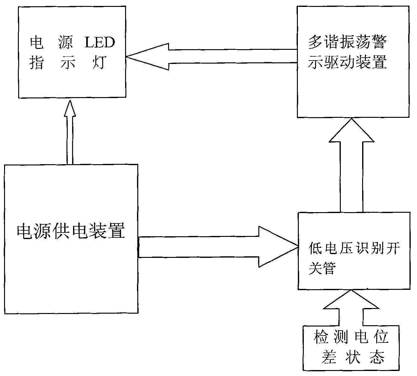
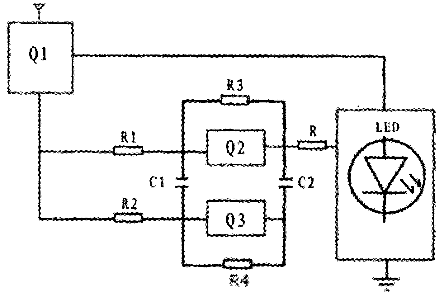
[0009] see figure 1 , figure 2 , a warning method for low-voltage detection according to the present invention, which includes the following steps: setting a detected power supply, a low-voltage identification switch, an oscillation unit, and a flash warning unit; the low-voltage identification switch detects the power supply using the principle of detecting potential difference The voltage level and the selection control of the corresponding device connection; if the detected power supply voltage is higher than a reference voltage value of 1.8V, the detected power supply is directly connected to the flash warning unit through the low voltage identification switch. At this time, the flash warning unit in the The LED power indicator light is always on when the power is on; if the detected power supply voltage is lower than or equal to a reference voltage value of 1.8V, the detected power supply is connected to the multi-vibrator warning drive device through the low voltage ide...


PUM


Abstract

The invention provides a low-voltage detection warning method which is characterized by comprising the following steps: (1) a detected power supply, a low-voltage identification switch, an oscillating unit and a flash warning unit are arranged; (2) the voltage of a power supply is detected according to the detection principle of a potential difference by the low-voltage identification switch, and device selection control is carried out; and (3) if the voltage of the detected power supply is higher than a reference voltage value, the detected power supply is directly connected to the flash warning unit by the low-voltage identification switch, and at the time that a power supply indicator light in the flash warning unit is normally on to prompt; if the voltage of the detected power supply is lower than or equal to the reference voltage value, the detected power supply is connected to the oscillating unit to drive the flash warning unit by the low-voltage identification switch; and at the time that the power supply indicator light in the flash warning unit is flickered to prompt. The invention also provides a low-voltage detection warning device for realizing the above method. According to the method and the device, the working power supply on the detected position is utilized to directly provide voltage for the power supply indicator to realize the voltage warning function and low cost.

Description

technical field [0001] The invention belongs to the field of electronic signal measurement, and in particular relates to a warning method and device for voltage level detection. Background technique [0002] The work of various modern electronic products requires power supply to provide work and operation, and there are countless products that use batteries to work. When using batteries to work, since the batteries have a certain amount of power, the internal voltage drop will naturally decrease after a period of use, which will affect the normal operation of the product. For some precision instruments or instruments that require continuous operation, other The normal operation of the work is of great significance to the functional effect it needs to achieve, and the prompt technology of voltage detection naturally becomes a necessary part of this type of product. Existing voltage detection devices are generally single-chip devices, which are connected outside the product w...

Claims


Application Information

Patent Timeline
IPC IPC(8): G01R19/165
Inventor 薛运林
Owner UNI TREND TECH (CHINA) CO LTD
Learn More