
Vibration subsoiling fertilizer applicator

A fertilizer applicator and subsoiling technology, which is applied to fertilization devices, soil preparation machinery, fertilizer distributors, etc., can solve the problems of tractor driver's physical discomfort, difficult adjustment of subsoiling interval, high bearing pressure, etc., and achieve compact and simple eccentric structure, Good working effect and reduced vibration

Inactive Publication Date: 2011-07-27
CHINA AGRI UNIV
View PDF4 Cites 19 Cited by
  • Summary
  • Abstract
  • Description
  • Claims
  • Application Information

AI Technical Summary

Problems solved by technology

The vibration mechanism of the vibrating subsoiler is a cantilever structure, resulting in a large shaft length and a large bearing pressure at the other end of the cantilever
And because the vibration of the vibrating subsoiler causes the tractor to vibrate, it is easy to make the tractor driver feel uncomfortable.
At present, the number of subsoiling rows and the subsoiling interval of the subsoiler are not easy to adjust

Method used


Image

  • Vibration subsoiling fertilizer applicator
  • Vibration subsoiling fertilizer applicator
  • Vibration subsoiling fertilizer applicator

Examples


Embodiment Construction

[0027] Below in conjunction with embodiment and accompanying drawing, the present invention will be described in further detail:

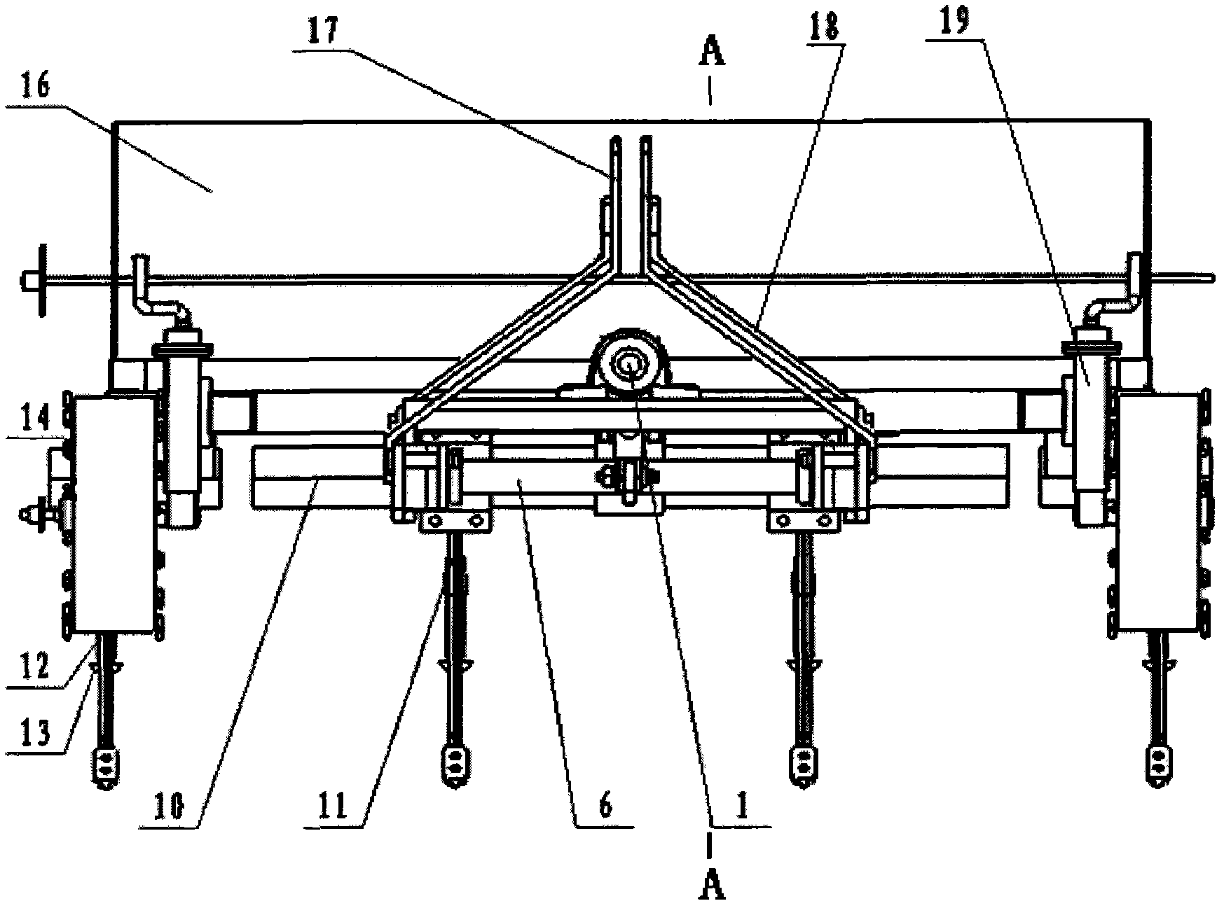
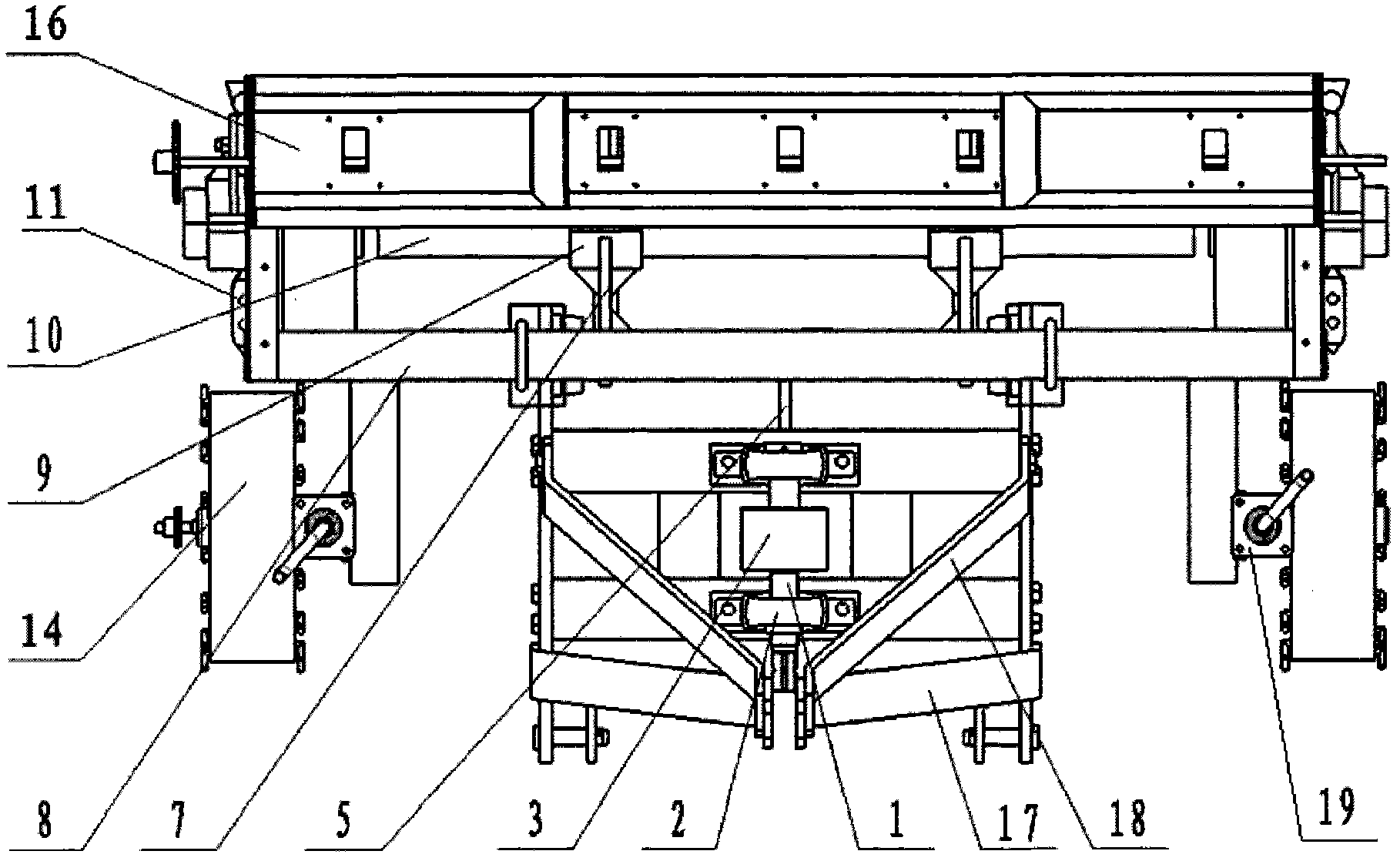
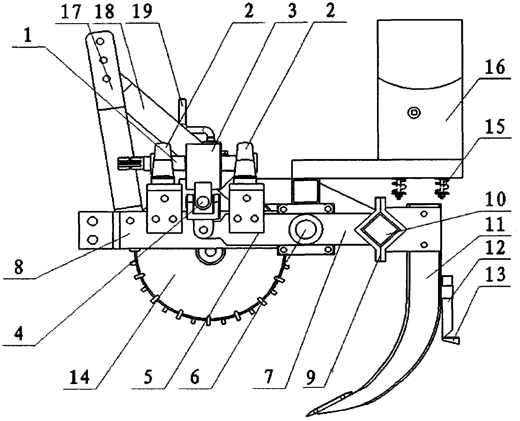
[0028] figure 1 For the embodiment structural representation of vibrating subsoiling fertilizer applicator 4 row work, figure 2 It is a top view schematic diagram of an embodiment working for 4 rows of vibrating subsoiling fertilizer applicators. The vibration subsoiling device, depth control device, fertilization device and traction device of the vibratory subsoiling fertilizer applicator are all installed on the Figure 5 on the rack shown. The vibrating subsoiling device is placed in the middle of the frame and at the rear of both sides. The vibrating subsoiling device is connected with the power output shaft of the tractor. The depth control device is placed on both sides of the frame. The fertilization device is placed at the rear of the frame. The traction device Placed at the front of the frame and connected to the tractor's traction dev...


PUM


Abstract

The invention relates to a vibration subsoiling fertilizer applicator, and belongs to the field of agricultural machines. The vibration subsoiling fertilizer applicator comprises a vibration subsoiling device, a depth control device, a fertilizer applying device and a traction device, wherein the vibration subsoiling device is arranged on the middle part of a machine frame and the rear parts on both sides of the machine frame and is connected with a power output shaft of a tractor; the depth control device is arranged on both sides of the machine frame; the fertilizer applying device is arranged on the rear part of the machine frame; and the traction device is arranged on the front part of the machine frame and is connected with a traction device of the tractor. In the vibration subsoiling fertilizer applicator, an eccentric mechanism has a bridge type structure of an eccentric shaft, an eccentric section of the eccentric shaft is in the middle, and both ends of the eccentric shaft are supported by bearings; the pressure applied by the eccentric shaft onto the bearings at both ends is reduced, so that the length of the eccentric shaft is shortened, and the eccentric mechanism is compact and simple; and in the vibration subsoiling device, a mode that part of subsoiling shovels vibrates actively is adopted, namely the subsoiling shovels in middle rows vibrate actively to loose soil, and the subsoiling shovels in two side rows vibrate passivity, so the vibration subsoiling device can loose the soil by vibrating and play the damping effect. The vibration subsoiling fertilizer applicator is suitable for the intertillage operation of subsoiling soil preparation and crops.

Description

technical field [0001] The invention belongs to the field of agricultural machinery, in particular to a vibrating subsoiler and fertilizer. Background technique [0002] Soil subsoiling refers to the use of a subsoiler to loosen the plow layer 5 to 15 cm below the plow layer, loosen the soil and deepen the thickness of the loose soil layer. As an important technology of soil cultivation, subsoiling has been paid more and more attention at home and abroad. Long-term plowing or stubble removal operations will cause the bottom of the plow to float up and the cultivated layer will become shallower. Finally, soil erosion will intensify and the soil will gradually degrade. The more degraded the soil, the lower the income of farmers and the lower the production efficiency. [0003] 1. Soil deep loosening technology can break the soil compaction, and then deepen the plowing layer. Soil subsoiling can break the hard plow bottom layer formed by plowing or stubble removal for many ye...

Claims


Application Information

Patent Timeline
IPC IPC(8): A01B49/06A01B35/02A01B35/20A01C15/00
CPCY02P60/21
Inventor 张东兴李霞付俊峰崔涛刘佳高娜娜王波刘媛媛胡国勇
Owner CHINA AGRI UNIV
Learn More