
Piezoelectric ceramic wafer type isolating signal transformer and manufacturing method thereof

A technology of piezoelectric ceramics and manufacturing methods, which is applied in the field of transformers, can solve the problems of complex manufacturing, high cost, and unsafety of transformers, and achieve the effects of easy realization of large-scale production, easy manufacturing, and cost reduction

Inactive Publication Date: 2011-07-20
MORNSUN GUANGZHOU SCI & TECH
View PDF5 Cites 3 Cited by
  • Summary
  • Abstract
  • Description
  • Claims
  • Application Information

AI Technical Summary

Problems solved by technology

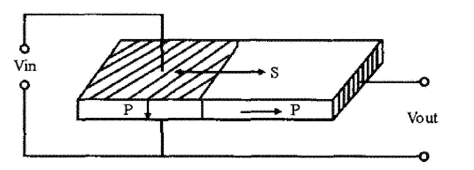
Its disadvantages are: the current three-terminal autotransformer input and output share the same ground, without the voltage isolation function of the input and output terminals, it is very unsafe in the transmission process in a relatively complicated working environment, and is not suitable for the field of signal isolation; Most of the current piezoelectric transformers are transformers that vibrate in the length or amplitude direction, and the conversion efficiency of transformers that vibrate in the radial direction is not as good as that
Magnetoelectric isolation transformers basically use wire-wound transformers. Two wire-wound magnetic core transformers are needed to realize the isolation of input and output. The disadvantages are: (1) The combination of two magnetic core transformers is relatively large It meets the requirements of sheet-type development; (2) The winding process of the transformer, the transformer has many windings, and the manufacturing cost of the transformer is high; (3) The wire-wound magnetic core transformer is easy to break down, easy to short-circuit between the windings, and the isolation effect is not good ; (4) Using two wire-wound transformers for isolation reduces the transmission efficiency of the entire signal
The optocoupler has a short life, is prone to light decay, and has a high cost

Method used


Image

  • Piezoelectric ceramic wafer type isolating signal transformer and manufacturing method thereof
  • Piezoelectric ceramic wafer type isolating signal transformer and manufacturing method thereof
  • Piezoelectric ceramic wafer type isolating signal transformer and manufacturing method thereof

Examples


Embodiment Construction

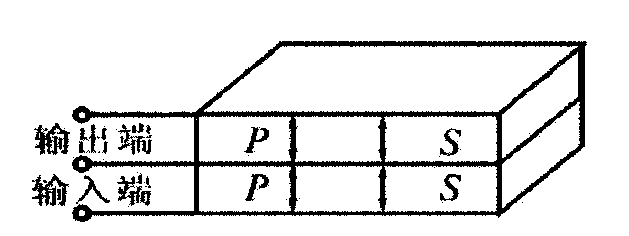
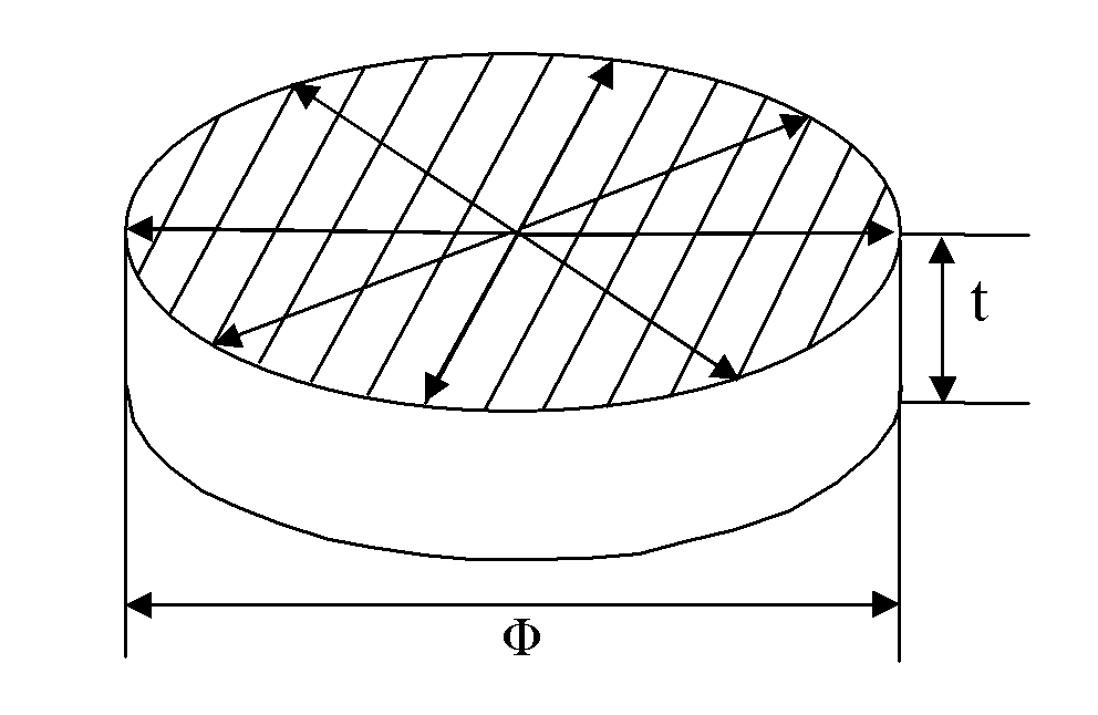
[0026] Fig. 4 is the specific embodiment of the present invention, as Pic 4-1 , Figure 4-2 , Figure 4-3 As shown, the piezoelectric ceramic isolation signal transformer is a wafer type, and mainly includes the following components: a ceramic body, an input part, an output part, a feedback part, and an isolation part.

[0027] The isolation part is distributed symmetrically along the diameter of the disc-shaped blank, and extends from the upper circular surface to the lower circular surface along the thickness direction, dividing the piezoelectric ceramic blank into two parts, the input and the output, forming a gap between the input and output parts. The first isolation zone without electrodes; the width of the first isolation zone is 0.5-2mm; the left side of the first isolation zone is the input part, the upper surface is covered with the upper electrode of the input part, and the lower surface is covered with the lower electrode of the input part; the input The upper s...


PUM

PropertyMeasurementUnit
diameteraaaaaaaaaa
widthaaaaaaaaaa
diameteraaaaaaaaaa

Abstract

The invention discloses a piezoelectric ceramic wafer type isolating signal transformer and a manufacturing method thereof. The transformer comprises a piezoelectric ceramic body, an input part, an output part and an isolating part, wherein the piezoelectric ceramic body is of a wafer type; the isolating part extends to another circular surface from one circular surface of the body in the thickness direction, so that the piezoelectric ceramic body is divided into two parts, namely the input part and the output part; a first isolating strip which is covered by an electrode is formed between the input part and the output part; and the input part and the output part are provided with covered electrodes on the upper surface and the lower surface of the body. The signal transformer has a voltage isolating function, high conversion efficiency, a simple structure and a small size.

Description

technical field [0001] The invention relates to a transformer, in particular to a piezoelectric ceramic disc-type isolated signal transformer used in the field of electronic industry such as signal transmission of low-power power electronics and a preparation method thereof. Background technique [0002] Since the 1980s, great breakthroughs have been made in the research and application of piezoelectric ceramic transformers, because piezoelectric transformers have the following four advantages over electromagnetic transformers: high boost voltage, high energy density and chip type small size. Piezoelectric transformer is a transformer that is different from the traditional concept in terms of material structure and working principle. It is made of ferroelectric materials through a series of processes such as high-temperature sintering and high-voltage polarization. , light weight, no breakdown, no fear of short circuit, high step-up ratio and other remarkable features, the ...

Claims


Application Information

Patent Timeline
Patent Type & Authority Applications(China)
IPC IPC(8): H01L41/107H01L41/04H01L41/24H10N30/40H10N30/03H10N30/80
Inventor 邓维体胡健仁陶武平李民
Owner MORNSUN GUANGZHOU SCI & TECH
Learn More