
Bending fatigue test machine for steel wire rope in case of alternating load

A technology of bending fatigue and steel wire rope, which is applied in the field of equipment in the field of testing technology, can solve the problem that the actual life of the test results of bending fatigue life of the steel wire rope is too different, it is not suitable for the prediction of the service life of the steel wire rope of the deep well friction hoist, and it cannot simulate the reality of the friction hoisting wire rope Working conditions and other issues to achieve the effect of improving safety and efficiency, simple structure, and easy control

Inactive Publication Date: 2011-07-13
CHINA UNIV OF MINING & TECH
View PDF5 Cites 19 Cited by
  • Summary
  • Abstract
  • Description
  • Claims
  • Application Information

AI Technical Summary

Problems solved by technology

The above-mentioned testing machine is a fatigue test device for steel wire ropes on cranes and elevators. Bending fatigue is the main cause of wire rope failure. Destruction is not the main cause of failure or only one of the reasons, so these fatigue test devices are not suitable for the prediction of the service life of deep well friction hoist wire rope
[0004] At present, there is no wire rope fatigue testing machine for testing the variable load fatigue life of deep well friction hoisting wire ropes, so it cannot simulate the actual working conditions of friction hoisting wire ropes. Using existing equipment to perform fatigue tests on friction hoisting wire ropes will only cause damage to the testing machine , the test results of the bending fatigue life of the steel wire rope are also too different from the actual life, and the experimental data is seriously distorted

Method used


Image

  • Bending fatigue test machine for steel wire rope in case of alternating load
  • Bending fatigue test machine for steel wire rope in case of alternating load
  • Bending fatigue test machine for steel wire rope in case of alternating load

Examples


Embodiment Construction

[0013] An embodiment of the invention will be further described below in conjunction with the accompanying drawings:

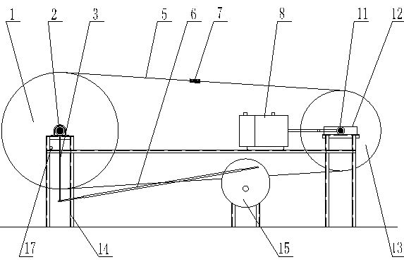
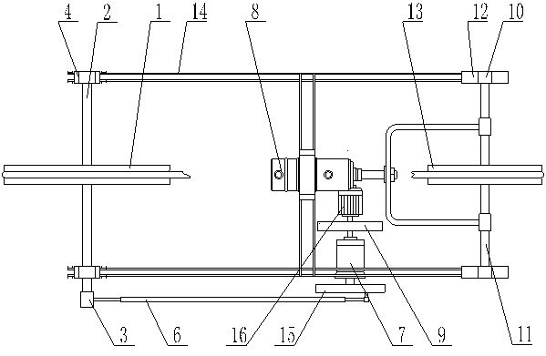
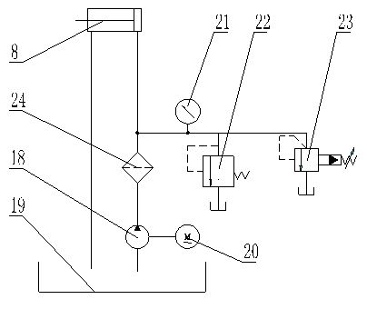
[0014] Such as figure 1 , 2 As shown, the steel wire rope variable load bending fatigue testing machine of the present invention is mainly composed of frame 14, driving wheel 1, drive shaft 2, tensioning shaft 11, tensioning wheel 13, steel wire rope 5, driving device, electro-hydraulic servo system, tensioning Mechanism and proximity switch 17 constitute, driving wheel 1 and tensioning wheel 13 are in the same vertical plane, and wire rope test piece 5 is wound on driving wheel 1 and tensioning wheel 13. Frame 14 is welded by section steel, symmetrical left and right, drive shaft 2 is fixed on the left side of frame 14 through bearing seat 4, tensioning shaft 11 is arranged in the guide groove 12 on the right side of frame 14 through limit bearing 10, The driving wheel 1 and the tensioning wheel 13 are arranged in the middle of the driving shaft 2 and the t...


PUM


Abstract

The invention provides a bending fatigue test machine for a steel wire rope in case of alternating load. The bending fatigue test machine comprises a frame, a steel wire rope test piece, a driving wheel, a drive unit, a proximity switch which are arranged on the frame, a power transmission system for driving the driving wheel to circularly rotate, and an electro-hydraulic servo system for supplying the alternating load to the steel wire rope test piece and a tensioning wheel, wherein the driving wheel, the drive unit and the proximity switch are arranged on the frame. In the invention, every time the tensioning wheel circularly rotates back and forth, the electro-hydraulic servo system changes the stress cycle of the steel wire rope once; then the proximity switch sends a counting signal; and finally the fatigue life of the steel wire rope is measured by counting cycle indexes. The test machine can be used for performing bending fatigue tests on various standard steel wire rope test pieces in the case of the alternating load, and applying various alternating loads on the steel wire rope test pieces. The test machine has a simple structure, and is easy to control.

Description

technical field [0001] The invention relates to equipment in the technical field of testing, in particular to a steel wire rope variable load bending fatigue testing machine suitable for testing the fatigue life of a steel wire rope under alternating loads. Background technique [0002] With the continuous development of mine mining, the number of domestic deep wells and ultra-deep wells is increasing. Due to the great lengthening of the friction hoist wire rope in deep mines, a series of problems have been brought to the operation of the hoist wire rope. The most prominent feature is the short service life. The average service life of the hoisting wire rope in the over 1,000-meter-deep wells such as the main shaft of Zhangxiao in Xuzhou and the main shaft of Dongguashan in Tongling is less than 8 months. The large number of broken wires and uneven broken wires seriously restrict the safety and economic efficiency of mine hoisting. According to theoretical analysis, the mai...

Claims


Application Information

Patent Timeline
IPC IPC(8): G01N3/36
Inventor 苗运江李婷叶圣伟
Owner CHINA UNIV OF MINING & TECH
Learn More