Washing machine
A drum-type washing machine, washing water technology, applied to other washing machines, washing machines with containers, washing devices, etc., can solve problems such as difficulty in implementation
- Summary
- Abstract
- Description
- Claims
- Application Information
AI Technical Summary
Problems solved by technology
Method used
Image
Examples
Embodiment approach 1
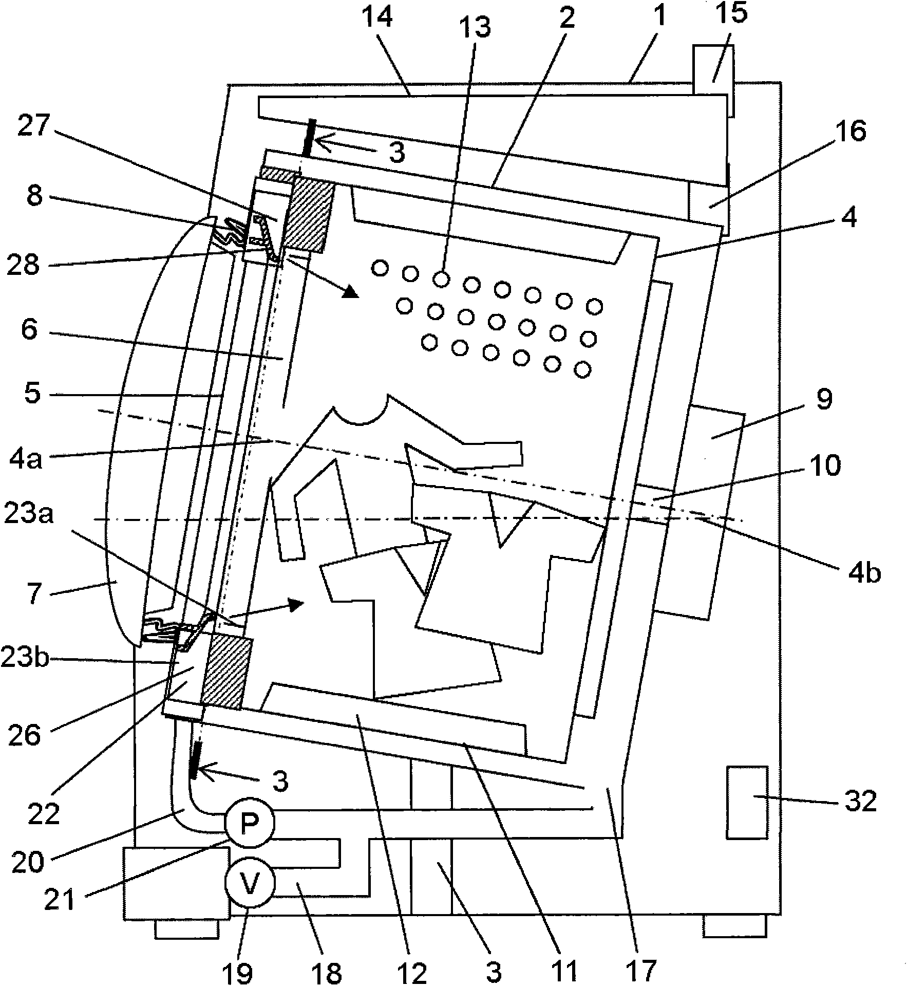
[0039] figure 1 A sectional view showing the front-loading washing machine in Embodiment 1 of the present invention.
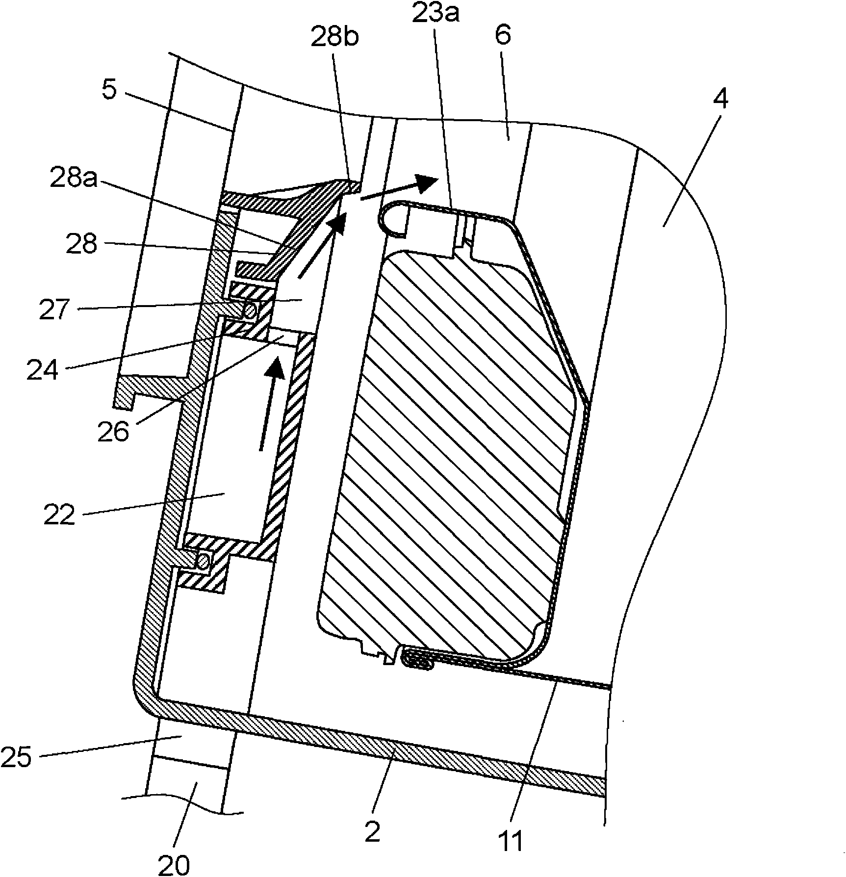
[0040] Such as figure 1 As shown, the drum type washing machine mainly includes: housing 2, water tank 2, suspension 3, rotating tank 4, openings 5, 6, door 7, motor 9, protrusion 12, water supply valve 15, drain valve 19, circulating waterway 20. Pump 21, nozzle waterway 22, nozzle 26.
[0041] In addition, a control unit 32 is provided at the rear lower part of the casing 1, and the control unit 32 is used to control the motor 9, the water supply valve 15, the drain valve 19, the pump 21, etc., and controls washing, rinsing, The actions of each step of dehydration.
[0042] A tank 2 formed in a cylindrical shape with a bottom is elastically supported in the casing 1 by a suspension 3 . Moreover, the rotary tank 4 formed in the shape of a bottomed cylinder is rotatably arrange|positioned in the water tank 2. As shown in FIG. The rotation axis 4a of the...
Embodiment approach 2
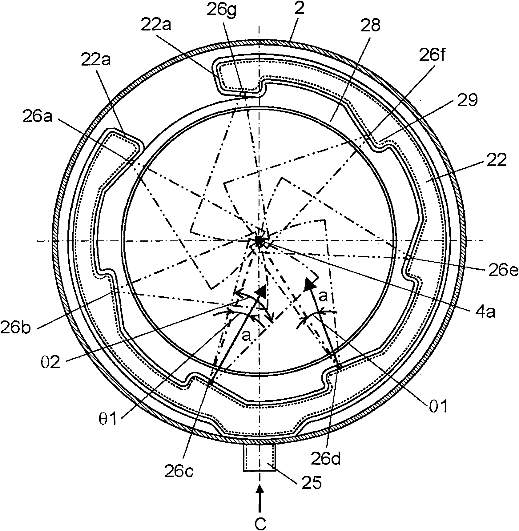
[0093] Figure 6 of the front-loading washing machine according to Embodiment 2 of the present invention figure 1 3-3 arrow direction view. This embodiment is different from the first embodiment in that the nozzle water channel 22 is provided at a position other than the direction directly below the rotation shaft 4a (vertical direction). In addition, other structures are the same as those of Embodiment 1, and the contents of Embodiment 1 are cited as the detailed description thereof.
[0094] Usually, since the washing water is accumulated in the lower part of the rotary tub 4, the washing water is supplied to the laundry at this position. Therefore, even if the washing water sprayed from the nozzle 26 is sprayed from the direction directly below (the vertical direction) of the rotating shaft 4a of the rotating tub 4, the effect is limited. Therefore, the nozzle water channel 22 is provided at a position other than the direction directly below (the vertical direction) of ...
Embodiment approach 3
[0104] Figure 7 of the front-loading washing machine in Embodiment 3 of the present invention figure 1 3-3 arrow direction view. In the present embodiment, nozzles 26a to 26f are configured to spray washing water toward positions other than the direction directly below the rotation shaft 4a (vertical direction). In addition, other structures are the same as those of Embodiment 1, and the contents of Embodiment 1 are cited as the detailed description thereof.
[0105] Since the washing water is accumulated in the lower part of the rotary tub 4, the washing water is supplied to the laundry present at this position. Therefore, the washing water is sprayed so that the spraying direction a of the washing water is directed to a position other than the direct downward direction (vertical direction) of the rotation shaft 4a. Accordingly, washing water can be efficiently and uniformly supplied to the entire laundry, thereby improving washing performance and rinsing performance.
PUM
 Abstract
Description
Claims
Application Information
 - R&D
- Intellectual Property
- Life Sciences
- Materials
- Tech Scout
- Unparalleled Data Quality
- Higher Quality Content
- 60% Fewer Hallucinations
Browse by: Latest US Patents, China's latest patents, Technical Efficacy Thesaurus, Application Domain, Technology Topic, Popular Technical Reports.
© 2025 PatSnap. All rights reserved.Legal|Privacy policy|Modern Slavery Act Transparency Statement|Sitemap|About US| Contact US: help@patsnap.com


