Light-emitting device and projector

一种发光装置、投影机的技术,应用在投影机领域,能够解决发光装置光学表现差等问题,达到光学表现佳的效果

Active Publication Date: 2011-07-06
CORETRONIC
View PDF0 Cites 1 Cited by
  • Summary
  • Abstract
  • Description
  • Claims
  • Application Information

AI Technical Summary

Problems solved by technology

Therefore, the relative positional relationship between each aspherical mirror and the LED chip of the corresponding light source module is easily affected by assembly tolerance, which makes the optical performance of each light emitting device after assembly poor.

Method used


Image

  • Light-emitting device and projector
  • Light-emitting device and projector
  • Light-emitting device and projector

Examples


Embodiment Construction

[0051] The aforementioned and other technical contents, features and effects of the present invention will be clearly presented in the following detailed description of the embodiments with reference to the drawings. The directional terms mentioned in the following embodiments, such as: up, down, left, right, front or back, etc., are only directions referring to the attached drawings. Accordingly, the directional terms are used to illustrate and not to limit the invention.

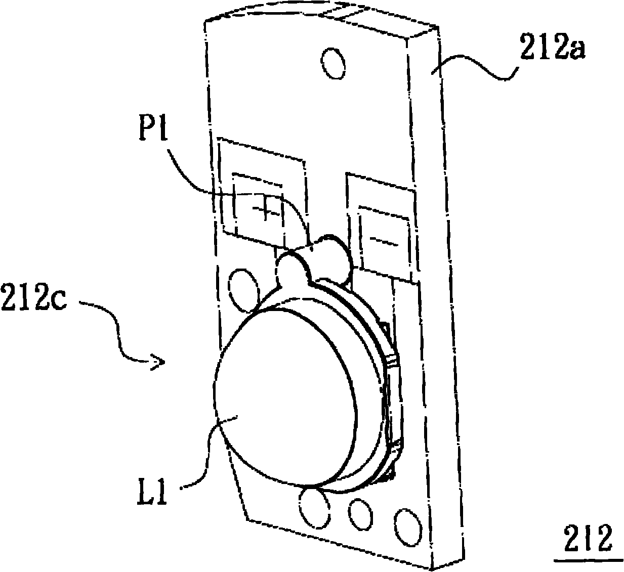
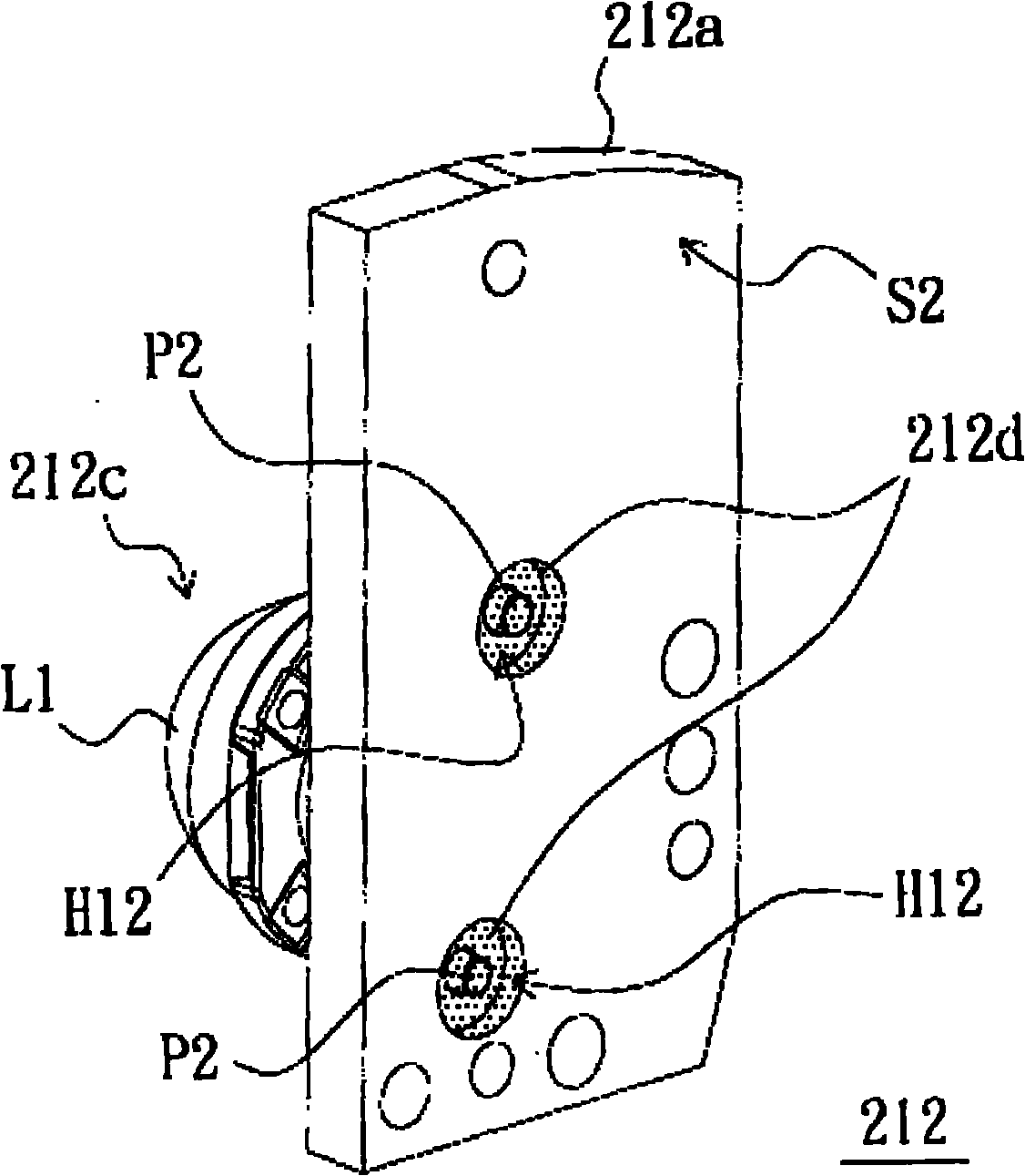
[0052] figure 1 A schematic top view of a projector according to an embodiment of the present invention is shown. Figure 2A draw figure 1 A three-dimensional schematic diagram of the light-emitting device. Figure 2B draw Figure 2A Another three-dimensional schematic diagram of the light-emitting device. Figure 2C draw Figure 2A A partially exploded schematic of the light-emitting device. Figure 2D draw Figure 2A Another partially exploded schematic of the light-emitting device. Figure 2E d...


PUM


Abstract

The invention relates to a light-emitting device which comprises a circuit board, a light-emitting element, a light-condensing element and glue, wherein the circuit board is provided with a plurality of penetration holes, and a first surface and a second surface which are opposite mutually; each penetration hole is provided with a first pathway and a second pathway; each first pathway is formed by the extension of the first surface into the circuit board; each second pathway is formed by the extension of the second surface into the circuit board and is communicated with one of the first pathways; the accommodating space of each second pathway is larger than the accommodating space of the corresponding first pathway; the light-emitting element is electrically connected to the first surface and is configured on the first surface; the light-condensing element is provided with a plurality of positioning posts; part of light-condensing element is configured on the light-emitting element; each positioning post penetrates through one of the first pathways and is positioned within the corresponding second pathway; the glue is configured in the second pathways to fix each positioning post in the corresponding penetration hole. The light-emitting device provided by the invention has a better optics performance.

Description

【Technical field】 [0001] The present invention relates to a light emitting device, and in particular to a projector with the light emitting device. 【Background technique】 [0002] Patents such as Taiwan Patent Publication Nos. M358248, M362415 and M261399 disclose various light emitting devices. However, the light emitting device applied to the projector is specially designed to provide a light beam with higher brightness and occupy less configuration space. [0003] A conventional projector includes an illumination system, a light valve and an imaging system. The illumination system is adapted to emit an illumination beam. The light valve is located on the transmission path of the illumination beam and is adapted to convert the illumination beam into an image beam. The imaging system is located on the transmission path of the image beam, and a projection lens of the imaging system is suitable for projecting the image beam onto a screen. [0004] The lighting system inclu...

Claims


Application Information

Patent Timeline
Patent Type & Authority Applications(China)
IPC IPC(8): F21S8/00F21V5/00F21V23/00G03B21/14
CPCH05K3/306H05K2201/09063H04N9/315H05K1/181G03B21/14H01L33/58H05K2201/10106H05K2203/167H04N9/3197H05K2201/10121G03B21/20Y02P70/50
Inventor 李鸿麟林晅铤
Owner CORETRONIC
Why Eureka
Try Eureka