
Vertical hydraulic bracket

A technology of vertical hydraulic support and hydraulic support, which is applied in mine roof supports, mining equipment, earthwork drilling and mining, etc., and can solve problems such as low coal recovery rate, danger, and high labor intensity

Inactive Publication Date: 2011-07-06
李泽宇
View PDF11 Cites 5 Cited by
  • Summary
  • Abstract
  • Description
  • Claims
  • Application Information

AI Technical Summary

Problems solved by technology

The chain-suspended hydraulic support (Chinese Patent Application No. ZL200520019152.2), which belongs to the sliding top beam hydraulic support category, has a strong adaptability to working faces with large inclination angles, but it is generally only used for inclination angles below 45°
Of course, some people have tried to use the hydraulic support at a larger inclination angle. For example, someone has used the fully mechanized mining hydraulic support in a working face with an angle of 60°. Standing on a large slope at a 60° angle for work and for long-distance travel is quite dangerous in itself, and it is difficult to stop once you roll down
It is for these reasons that for many years people have been mining the steeply inclined thick coal seams with the method of horizontally segmented top coal mining, and the thinner steeply inclined coal seams have to be mined by the old high-drop coal mining method. Therefore, it is not only labor-intensive, but also the coal recovery rate is low. Some thinner steeply inclined coal seams are even simply classified as unminable coal seams and discarded.

Method used


Image

  • Vertical hydraulic bracket
  • Vertical hydraulic bracket
  • Vertical hydraulic bracket

Examples


Embodiment Construction

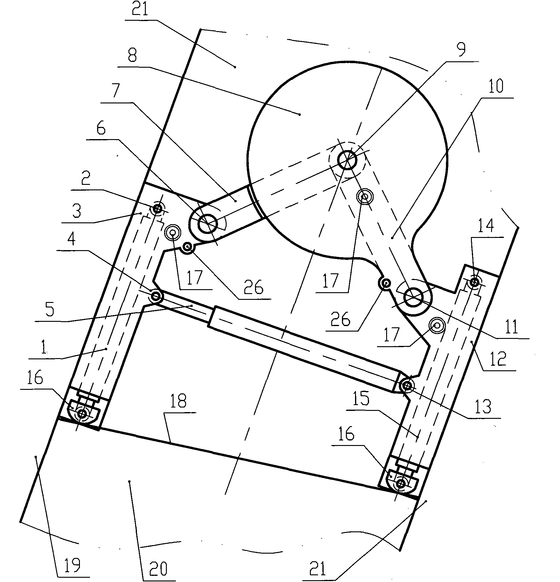
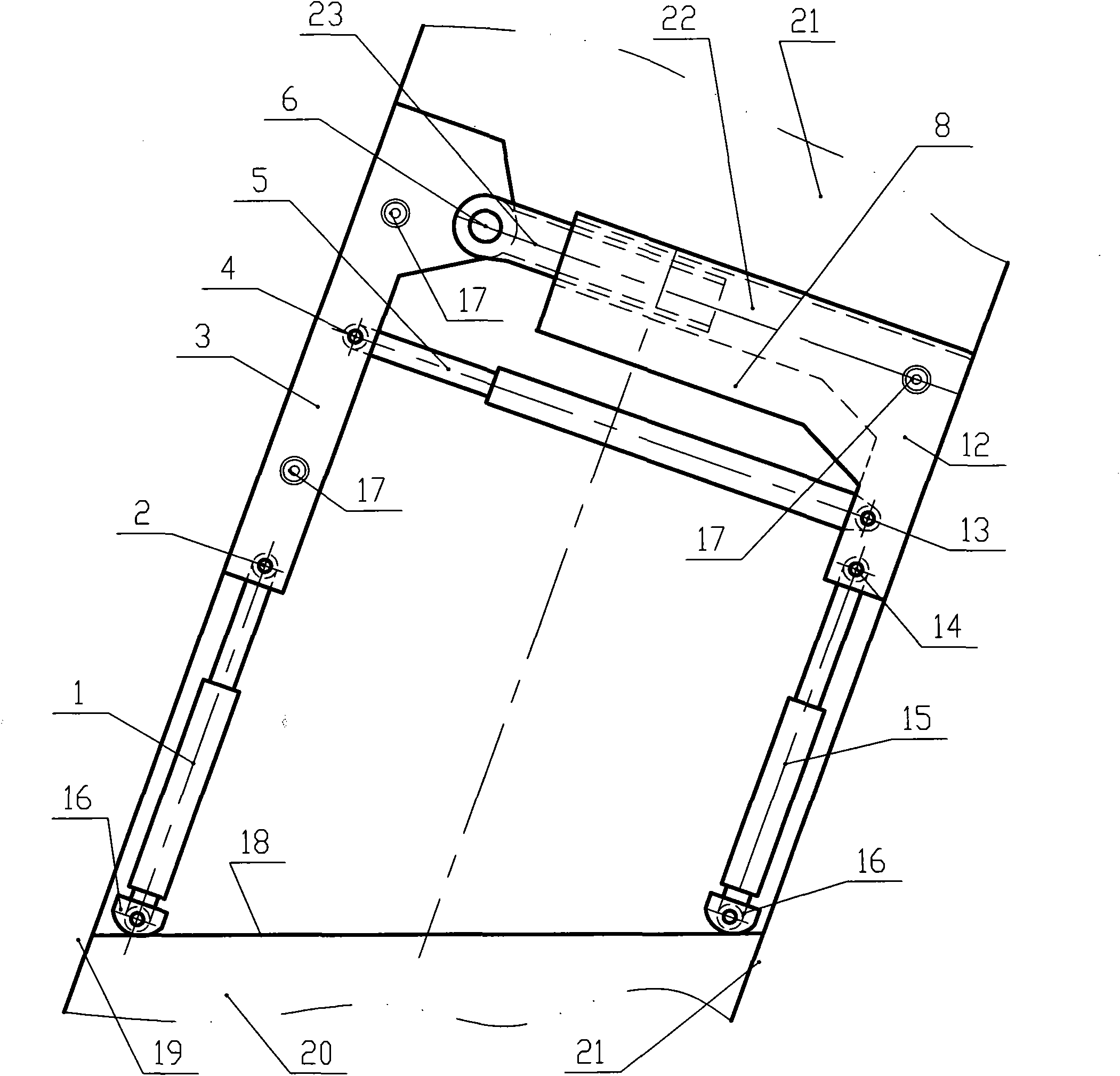
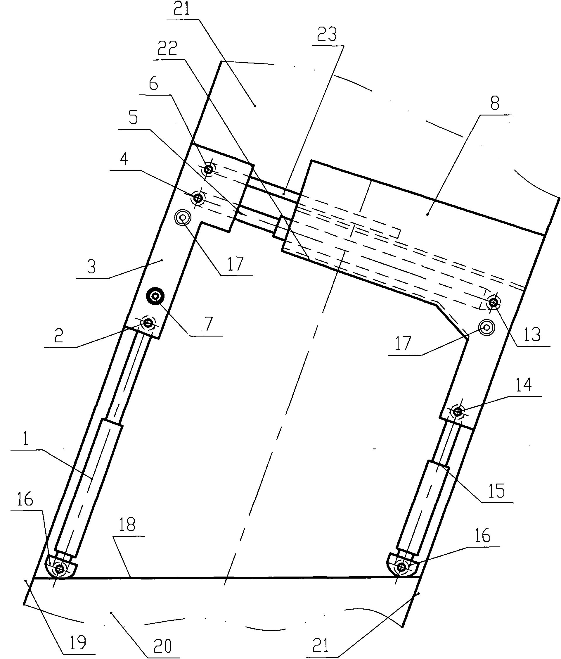
[0021] figure 1 A front view of the first embodiment of a vertical hydraulic support of the present invention is given. It includes roof beam 3, bottom beam 12, upper folded beam 7, lower folded beam 10, and not only includes roof support column 5 supporting the roof, but also supports wall columns supported on the coal wall. The top siding column 1 and the bottom siding column 15 close to the bottom plate. Among them, the upper end of the roof support wall column 1 is hinged with the top beam 3, and the lower end is supported on the coal wall 18. When the coal wall is soft or needs to be pulled down, the lower end is supported on the coal wall 18 through the column shoe 16 connected thereto; One end of the support column 5 is hinged to the top beam 3 through a hinge 4, and the other end is hinged to the bottom beam 12 through a hinge 13; It is hinged with the upper end of the lower folding beam 10, and the lower end of the lower folding beam 10 is hinged with the bottom bea...


PUM


Abstract

The invention discloses a vertical hydraulic bracket used for an underground heavy pitch coal mining working surface of a coal mine, which comprises a supporting device, a bracket moving device, a recrement stopping device, and a bracket adjusting device. The vertical hydraulic bracket is characterized in that at least one of hydraulic props forming the supporting device is a wall support prop; the upper end of the wall support prop is hinged with the vertical hydraulic bracket; the lower end of the wall support prop is supported on a coal wall; in the process of moving the bracket, the wall support prop bears the dead weight of the vertical hydraulic bracket and the loads of the recrement on the bracket; meanwhile, the wall support prop can also serve as a bracket moving cylinder; the bracket moving direction of the hydraulic bracket is downwards along the inclined direction of a coal seam; a person stands on the approximately horizontal coal walls to operate; therefore, the dangers that operating personnel in the heavy pitch working surface roll down along large-obliquity slopes and large lump coals roll along sharp slopes hurt people are avoided. The vertical hydraulic bracket is suitable for being used in 45-90 degree working surfaces.

Description

technical field [0001] The invention relates to a hydraulic support for a sharply inclined coal mining face under a coal mine. Background technique [0002] Hydraulic support is divided into two categories: fully mechanized mining hydraulic support and sliding roof beam hydraulic support. Both of these two types of hydraulic supports include top beams, hydraulic props for supporting the roof, and moving cylinders specially used for moving frames. In the gently inclined working face and inclined working face, for example, fully mechanized mining hydraulic support is generally used in the working face with an inclination angle less than 20°. The chain-suspension hydraulic support (Chinese patent application number ZL200520019152.2), which belongs to the sliding roof hydraulic support category, has a strong adaptability to large-inclination working faces, but it is generally only used at an inclination angle below 45°. Of course, some people have tried to use the hydraulic su...

Claims


Application Information

Patent Timeline
IPC IPC(8): E21D23/04E21D23/26E21D23/03
Inventor 李泽宇
Owner 李泽宇
Learn More