Eureka AIR delivers breakthrough ideas for toughest innovation challenges, trusted by R&D personnel around the world.

Omnidirectionally radiated ultra wideband antenna

An ultra-wideband antenna and omnidirectional radiation technology, which is applied in the direction of antenna, resonant antenna, and mid-position feed between antenna endpoints, can solve problems such as poor omnidirectionality, narrow application range, and uneven signals, and achieve uniform reception, The effect of convenient power feeding and wide application range

Active Publication Date: 2013-08-07
HARBIN INST OF TECH
View PDF3 Cites 0 Cited by
  • Summary
  • Abstract
  • Description
  • Claims
  • Application Information

AI Technical Summary

Problems solved by technology

[0003] The present invention solves the problem that the omnidirectionality of the H-plane pattern of the existing disc monopole antenna is very poor, and the signals received in all directions are not uniform, resulting in a narrow application range, and further provides an omnidirectional radiation ultra-wideband antenna

Method used

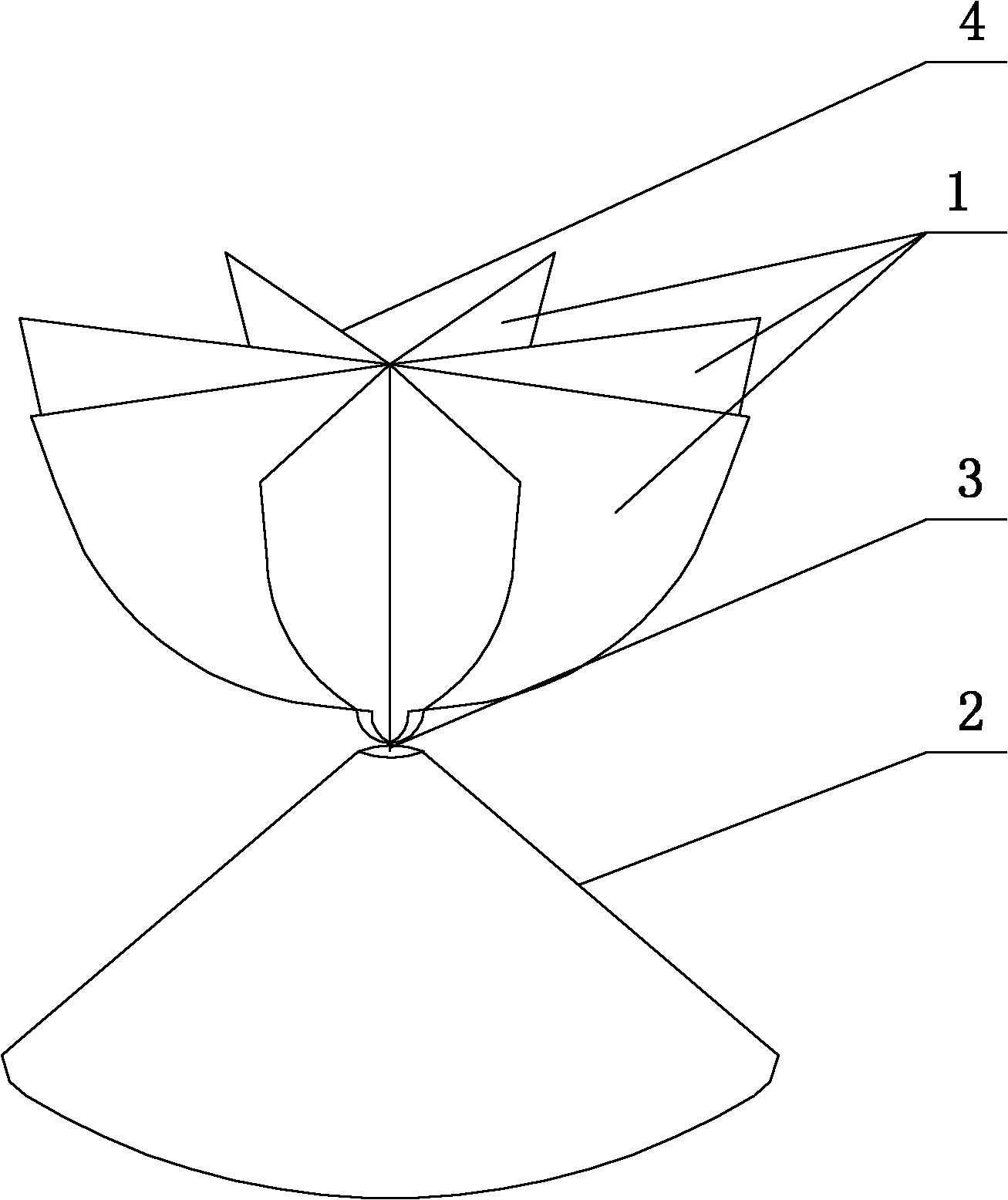

Image

  • Omnidirectionally radiated ultra wideband antenna
  • Omnidirectionally radiated ultra wideband antenna
  • Omnidirectionally radiated ultra wideband antenna

Examples


specific Embodiment approach 1

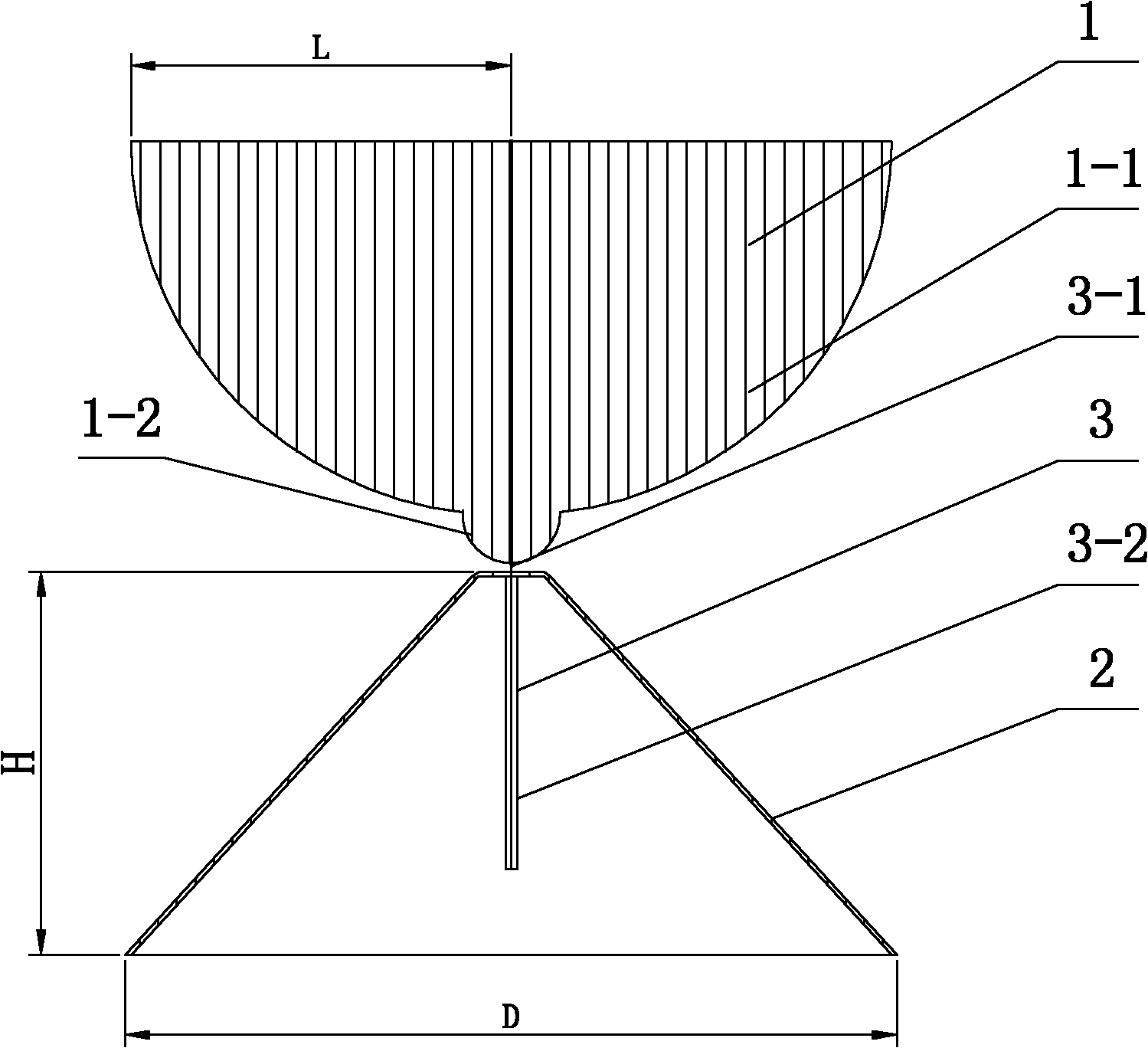
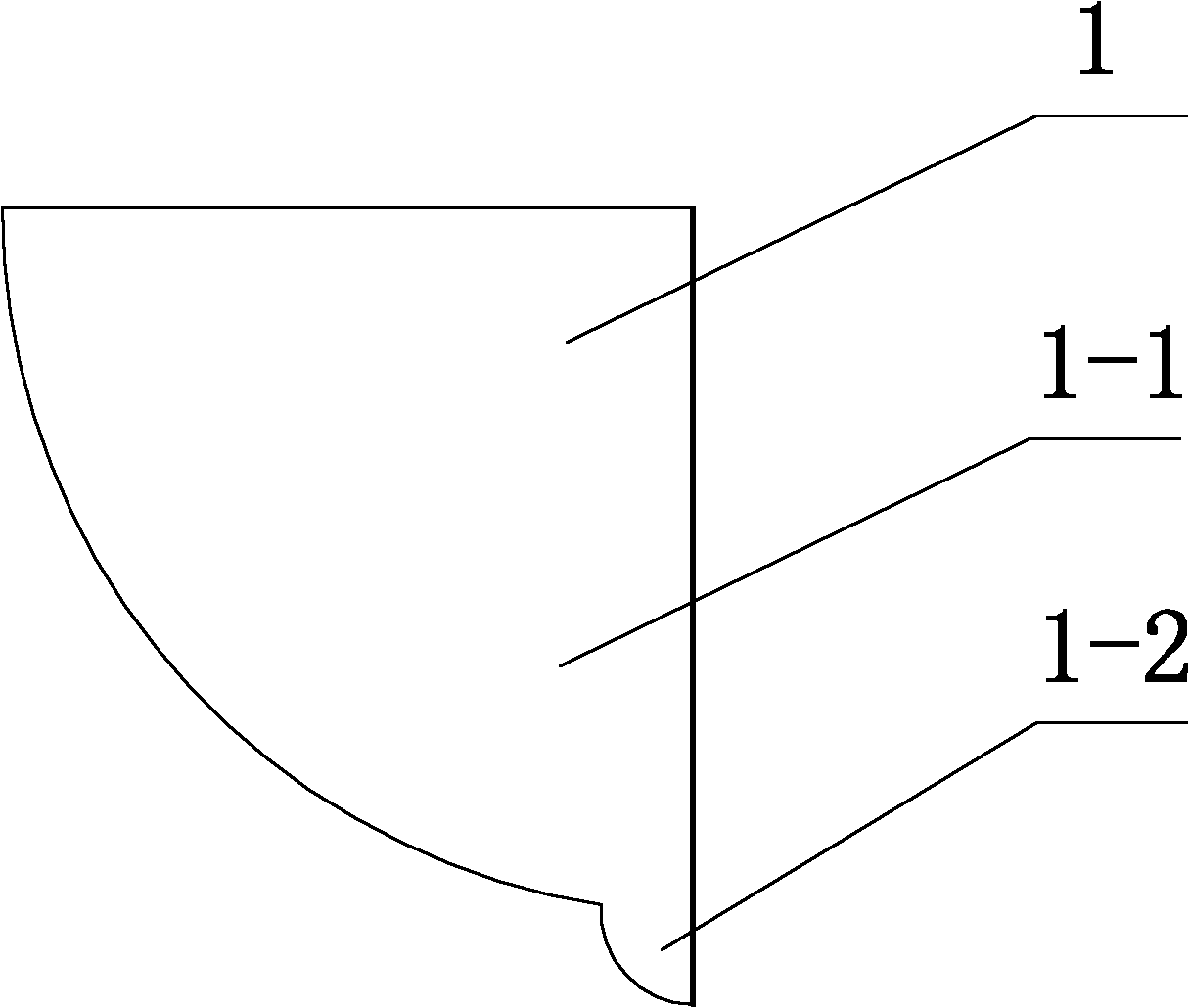
[0009] Specific implementation mode one: combine Figure 1~3 Explain that the omnidirectional radiation ultra-wideband antenna of the present embodiment is made up of eight metal sheets 1, a conical cylinder 2 and a feeding coaxial line 3, and each metal sheet 1 is composed of a large quarter circular sheet 1-1 and The small quarter circle is composed of 1-2, the large quarter circle 1-1 and the small quarter circle 1-2 are connected up and down as a whole and are located on the same plane, the large quarter circle The tail end of the arc of 1-1 is connected with the head end of the arc of the small quarter disc 1-2 on the same side, and the diameter in the vertical direction of the large quarter disc 1-1 is the same as that of the small quarter disc 1-2. The diameters of one-half of the circular sheet 1-2 in the vertical direction are on the same axis, and the eight metal sheets 1 are arranged in a star shape, and the eight metal sheets 1 are evenly arranged with the vertical...

specific Embodiment approach 2

[0010] Specific implementation mode two: combination figure 2 Explain that the feeding coaxial line 3 in this embodiment is composed of an inner core 3-1 and a shielding layer 3-2, the upper end of the shielding layer 3-2 is fixed on the upper end of the conical cylinder 2, and the lower end of the inner core is formed by Inserted in the shielding layer 3-2 from top to bottom. Other compositions and connections are the same as those in Embodiment 1.

specific Embodiment approach 3

[0011] Embodiment 3: The characteristic impedance of the feeding coaxial line 3 in this embodiment is 50 ohms. With such a design, the characteristic impedance of common coaxial cables is 50 ohms, and it is convenient to select existing coaxial cables. Other compositions and connections are the same as those in the first or second embodiment.


PUM


Abstract

The invention relates to an ultra wideband antenna, in particular to an omnidirectionally radiated ultra wideband antenna. The problems that the conventional disc monopole antenna has a low omnidirectional H plane directional diagram, and receives omnidirectional signals in a nonuniform mode, so that an application range is narrow, are solved. Eight metal sheets are arranged in a star mode, and are uniformly distributed by taking a vertical side as a center to form a metal frame; the outside diameter of the upper end of the metal frame is larger than the outside diameter of the lower end; themetal frame is positioned over a conical cylinder; the outside diameter of the upper end of the conical cylinder is smaller than the outside diameter of the lower end; a feed coaxial cable is positioned in the conical cylinder; the upper end of a feed coaxial cable shielding layer is fixedly arranged at the upper end of the conical cylinder; and the upper end of an inner core of the feed coaxial cable is fixedly connected with the bottom end of the metal frame. By the omnidirectionally radiated ultra wideband antenna, the eight metal sheets are uniformly distributed by taking the vertical side as the center to form the metal frame, so that the omnidirectional H plane directional diagram is greatly improved, the omnidirectional signals can be uniformly received, and the application range is wide.

Description

technical field [0001] The invention relates to an ultra-wideband antenna. Background technique [0002] The existing disk monopole antenna adopts the combined structure of metal disk and metal floor, such as Figure 4 shown. Although the disk monopole antenna has a very wide operating frequency band, the omnidirectionality of the H-plane pattern is very poor, and the signals received in all directions are uneven, and the application range is narrow. It is not suitable for EMC sensitivity testing, spectrum measurement, Signal interference and other fields that require high antenna omnidirectionality. Contents of the invention [0003] The present invention solves the problem that the omnidirectionality of the H-plane pattern of the existing disc monopole antenna is very poor, and the signals received in all directions are not uniform, resulting in a narrow application range, and further provides an omnidirectional radiation ultra-wideband antenna . [0004] The technica...

Claims


Application Information

Patent Timeline
Patent Type & Authority Patents(China)
IPC IPC(8): H01Q5/00H01Q9/28H01Q5/25
Inventor 邱景辉陈立甲林澍张鹏宇王文宁
Owner HARBIN INST OF TECH
Why Eureka
Eureka Blog
Learn More