Door lock structure and steam box
A door lock structure and a technology for a steam box, which are applied in the field of steam boxes, can solve the problems of complex process and high cost, and achieve the effects of simple process, low cost, and simple door lock structure and technology.
- Summary
- Abstract
- Description
- Claims
- Application Information
AI Technical Summary
Problems solved by technology
Method used
Image

Examples
specific Embodiment 1
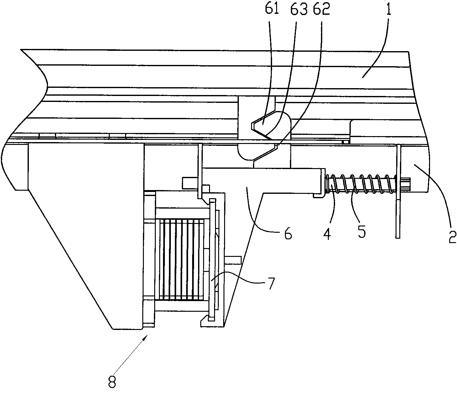
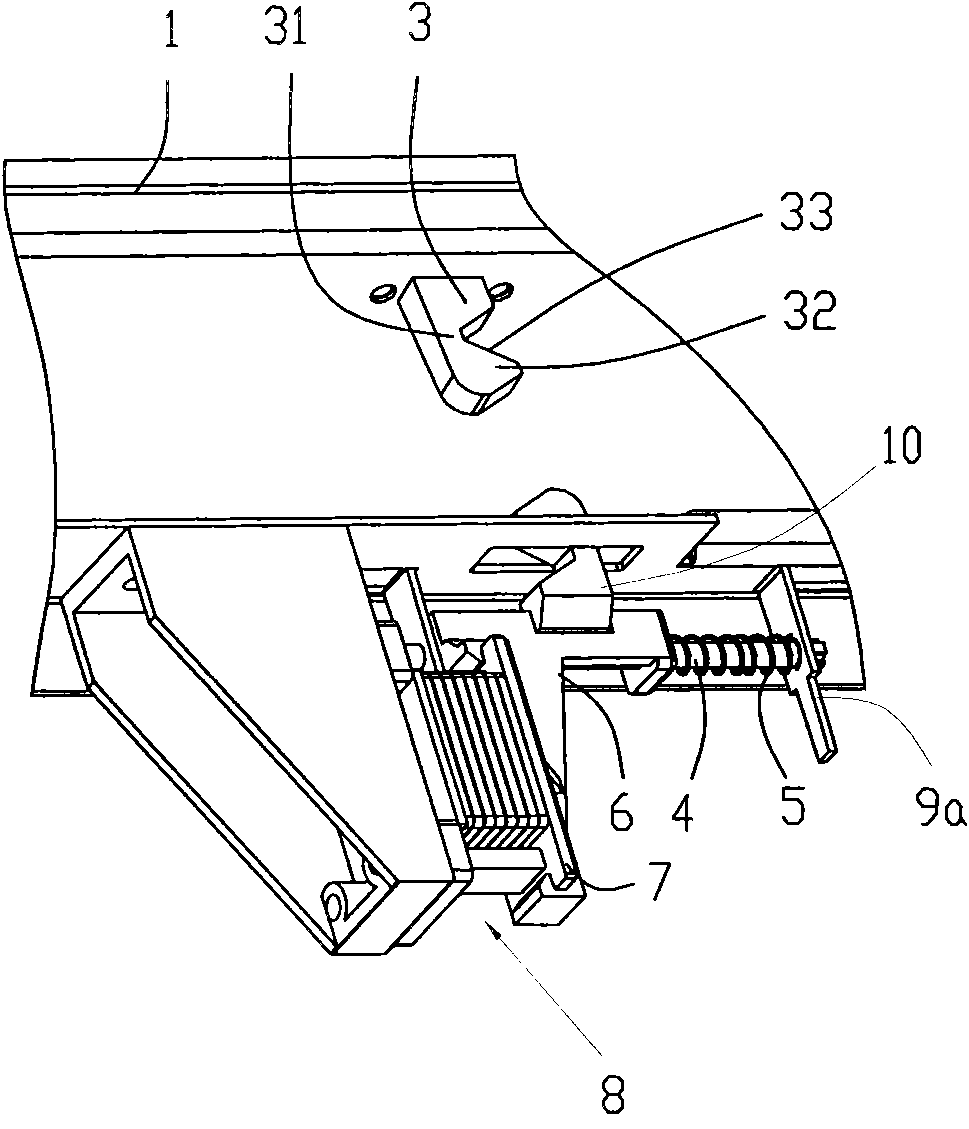
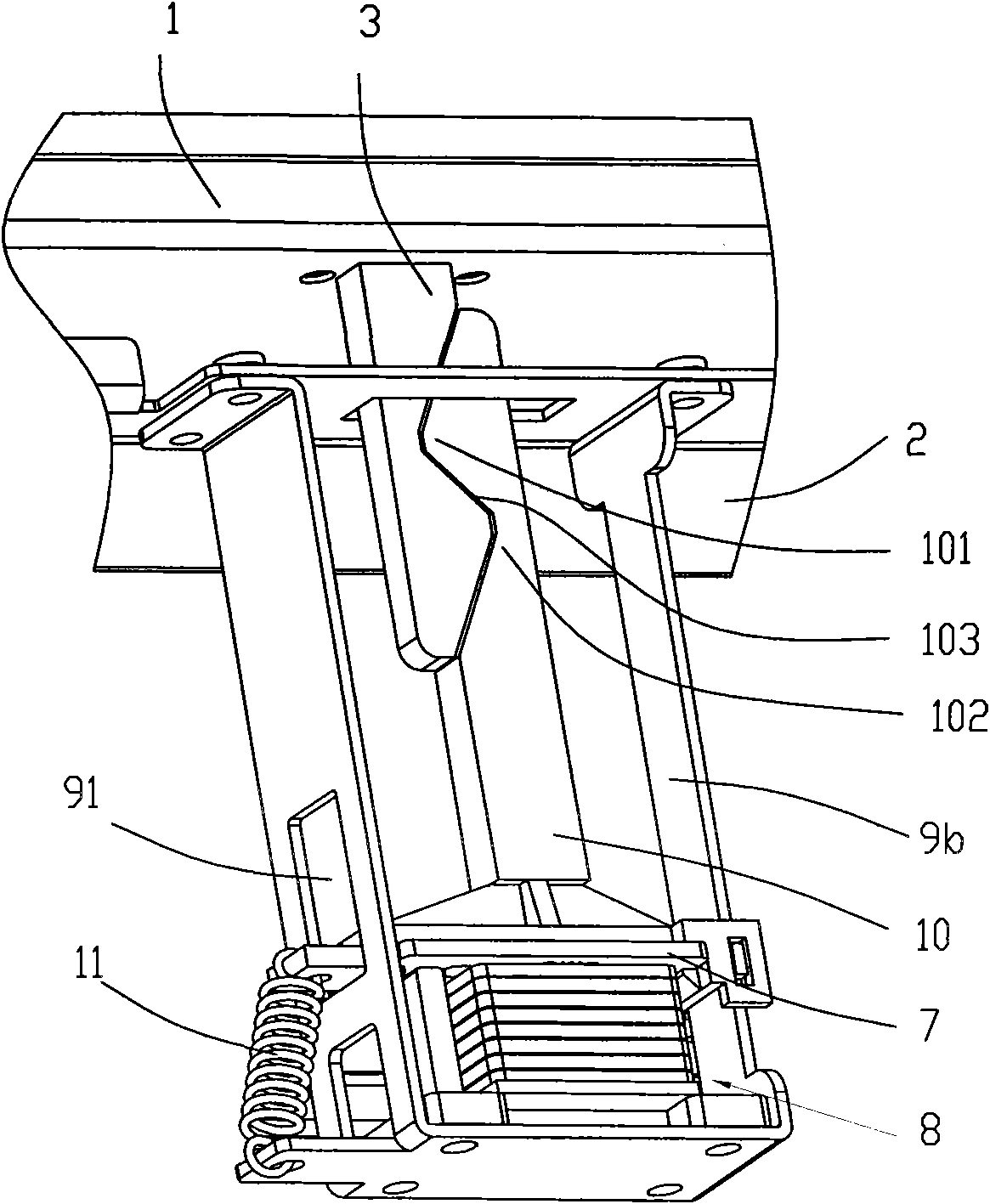
[0034] Such as figure 1 , figure 2As shown, the present invention includes a door cover 1, a furnace cavity support 2 and a control circuit, and the door cover 1 is fixedly provided with a door buckle 3, and the door buckle 3 is provided with a V-shaped groove I 31 and a V-shaped convex Edge I 32. The furnace cavity support 2 is provided with a support I 9a, the support I 9a is provided with a guide rod 4, the guide rod 4 is sleeved with a spring I 5 and a slide block 6, and the spring I 5 and the The slider 6 can move along the guide rod 4 . The slider 6 is provided with a hook 10, and the hook 10 is respectively provided with a V-shaped flange II 61 and a V-shaped recess which are matched with the V-shaped groove I 31 and the V-shaped flange I 32. Slot II 62. The V-shaped groove I 31 and the V-shaped flange I 32 have a common surface I 33 , and the V-shaped flange II 61 and the V-shaped groove II 62 have a common surface II 63 .
[0035] The principle and working proce...
specific Embodiment 2
[0037] Such as figure 1 , figure 2 As shown, compared with the solution in the first embodiment, the main difference of this embodiment is that: the slider 6 is provided with an iron-absorbing piece 7, and the furnace cavity support 2 is provided with an iron-absorbing piece 7 corresponding to the Matched iron core assembly 8. When the control circuit is powered on, the iron core assembly 8 absorbs the iron-absorbing piece 7 , and when the control circuit is powered off, the iron-core assembly 8 delays releasing the iron-absorbing piece 7 . This technical solution is superior to the solution in the first embodiment in that: first cut off the power and then delay opening the door, so as to avoid scalding the user by superheated steam when opening the door. If you want to open the door of the steam box when the steam box is not powered off, the user cannot open the door of the steam box because the iron core assembly 8 will hold the iron-absorbing sheet 7 when the steam box i...
specific Embodiment 3
[0038] Such as Figure 5 As shown, the present invention includes a door lock 12a, a steam chamber 13 and a steam box door 14. The door lock 12a may be the door lock 12a described in the first embodiment, or the door lock 12a described in the second embodiment.
PUM
 Abstract
Description
Claims
Application Information
 - R&D
- Intellectual Property
- Life Sciences
- Materials
- Tech Scout
- Unparalleled Data Quality
- Higher Quality Content
- 60% Fewer Hallucinations
Browse by: Latest US Patents, China's latest patents, Technical Efficacy Thesaurus, Application Domain, Technology Topic, Popular Technical Reports.
© 2025 PatSnap. All rights reserved.Legal|Privacy policy|Modern Slavery Act Transparency Statement|Sitemap|About US| Contact US: help@patsnap.com