
Long-stroke DC linear motor and control system thereof

A linear motor and control system technology, applied in the direction of AC motor control, control system, propulsion system, etc., can solve the problems of high power and high precision, improve linearity, reduce winding inductance and magnetic circuit cross-sectional area, The effect of suppressing thrust fluctuations

Active Publication Date: 2011-06-15
HARBIN INST OF TECH
View PDF5 Cites 3 Cited by
  • Summary
  • Abstract
  • Description
  • Claims
  • Application Information

AI Technical Summary

Problems solved by technology

[0009] In order to solve the problem that the traditional DC linear motor and its control system have only one set of windings and one drive controller, and it is difficult to realize high power and high precision at the same time, the present invention proposes a long-stroke DC linear motor and its control system

Method used


Image

  • Long-stroke DC linear motor and control system thereof
  • Long-stroke DC linear motor and control system thereof
  • Long-stroke DC linear motor and control system thereof

Examples


specific Embodiment approach 1

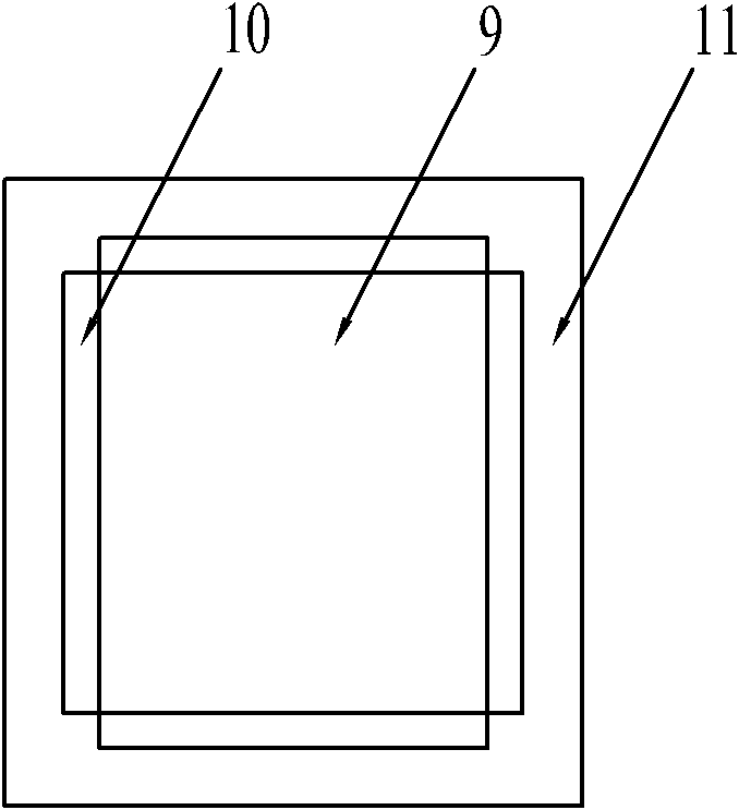
[0021] Specific implementation mode one: combine figure 2 Describe this embodiment, this embodiment is made up of primary and secondary; There is an air gap between said primary and secondary; , a power winding 7 and an even number of compensation windings 8;

[0022] The magnetic yoke part is composed of an upper magnetic yoke 1, a middle magnetic yoke 2, a lower magnetic yoke 3 and two side magnetic yokes 4; an upper magnetic yoke 1, a middle magnetic yoke 2 and a lower magnetic yoke 3 are arranged parallel to each other; the setting directions of the upper magnetic yoke 1, the middle magnetic yoke 2 and the lower magnetic yoke 3 are all parallel to the direction of motion; the upper magnetic yoke 1, the middle magnetic yoke 2, the lower magnetic yoke 3 and the The two lateral guide yokes 4 are enclosed to form a rectangular guide yoke part;

[0023] The even number of flat permanent magnets 5 are respectively arranged on the magnetically permeable yoke parts;

[0024] T...

specific Embodiment approach 2

[0029] Specific implementation mode two: combination image 3 Describe this embodiment, the difference between this embodiment and the specific embodiment is that the number of the compensation winding 8 is two; Two compensation windings 8 are located at both ends of the control winding 6 respectively. Other compositions and connection methods are the same as those in Embodiment 1.

specific Embodiment approach 3

[0030] Specific implementation mode three: combination Figure 4 Describe this embodiment, the difference between this embodiment and the specific embodiment is that the number of the compensation windings 8 is four; the four compensation windings 8 are divided into two groups; On the two lateral guide yokes 4 between the magnetic guide yoke 1 and the middle guide yoke 2; the other set of compensation windings 8 are respectively installed on the two side guide magnetic yokes between the lower guide yoke 3 and the middle guide yoke 2 Yoke 4 on. Other compositions and connection methods are the same as those in Embodiment 1.


PUM


Abstract

The invention discloses a long-stroke DC linear motor and a control system thereof, which relate to the liner motors and aim to solve the problems of difficulties in the simultaneously achievement of high power and high accuracy because the conventional DC linear motor and the control system thereof only have a set of winding and a drive controller. An even number of flat constant magnetic permanent magnets are arranged on magnetic conductive yoke parts respectively. A control winding is uniformly wound on the outer surface of a middle magnetic conductive yoke. A plurality of sections of power windings are uniformly and closely wound on the outer surface of the control winding. An even number of compensation windings are wound on the magnetic conductive yoke parts respectively. A secondary part adopts a double-side secondary part. A main permanent magnet is a flat permanent magnet. Four elongated auxiliary permanent magnets are arranged on the four sides of the main permanent magnet respectively. A permanent magnet holder is fixedly arranged about the four elongated auxiliary permanent magnets. The long-stroke DC linear motor and the control system thereof have the advantages of achieving high thrust and high accuracy in acceleration and deceleration control, achieving high accuracy in speed and position control, improving current and thrust dynamic response and the like, and are applicable to various DC linear control systems.

Description

technical field [0001] The invention relates to a direct current linear motor and its control system. Background technique [0002] The DC linear motor manufactured based on the Ampere force principle is more and more used in various linear motion control systems because of its simple structure, small size, small thrust fluctuation, high reliability, and high energy conversion efficiency. Coupled with the characteristics of fast, smooth, no cogging, and no hysteresis response of DC linear motors, DC linear motors can be well used in servo control systems that require high speed, high acceleration, and high thrust response. In the traditional DC linear motor structure, the permanent magnet is flat plate, magnetized in parallel, fixed on the underside of the upper yoke plate and the upper side of the lower yoke plate of a “day”-shaped magnetic yoke, and the permanent magnets on the upper and lower yoke plates The direction of magnetization is opposite, such as figure 1 shown...

Claims


Application Information

Patent Timeline
IPC IPC(8): H02K41/035H02K1/27H02P25/08H02P25/064
Inventor 寇宝泉张赫张鲁
Owner HARBIN INST OF TECH
Learn More