Solar energy-driven cogeneration device
A technology of solar energy and solar heat collection, applied in the direction of using solar energy to generate mechanical power, solar thermal power generation, steam engine devices, etc., can solve the problems of single electric energy output, environmental heat pollution, and ineffective utilization, so as to improve utilization rate and overall efficiency The effect of increasing and reducing the collector area
Inactive Publication Date: 2011-06-15
SOUTHEAST UNIV
View PDF4 Cites 10 Cited by
- Summary
- Abstract
- Description
- Claims
- Application Information
AI Technical Summary
Problems solved by technology
In existing technologies or devices, the proportion of thermal energy converted into mechanical energy from solar energy is limited, and a large part of the energy is directly dissipated by the condenser without effective use, causing certain thermal pollution to the environment. The heat source used for hot water can realize the cascade utilization of heat energy; at the same time, most systems only output a single electric energy, and the overall efficiency is not high
Method used
View moreImage
Smart ImageViewing Examples
Examples
Embodiment 1
Embodiment
Login to View More PUM
 Abstract
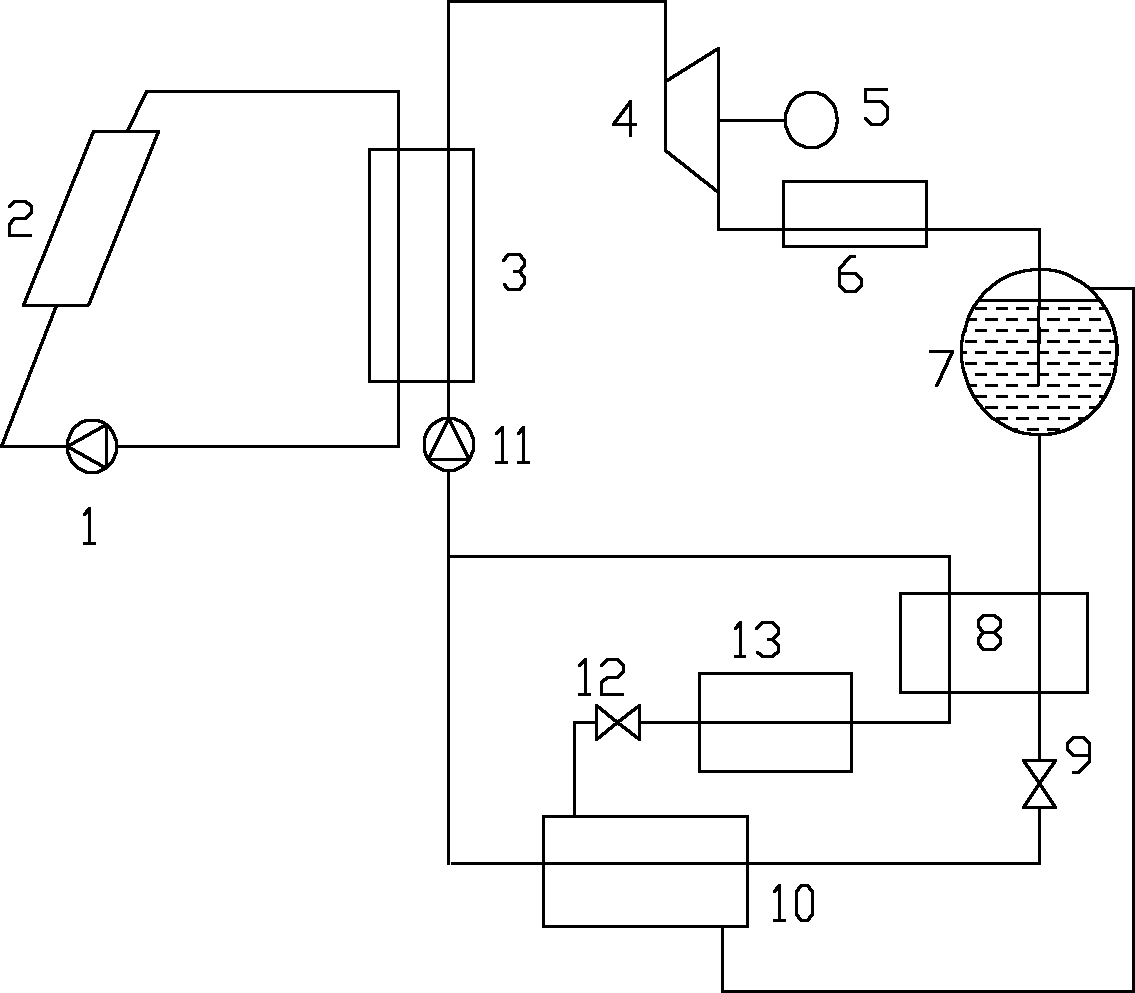
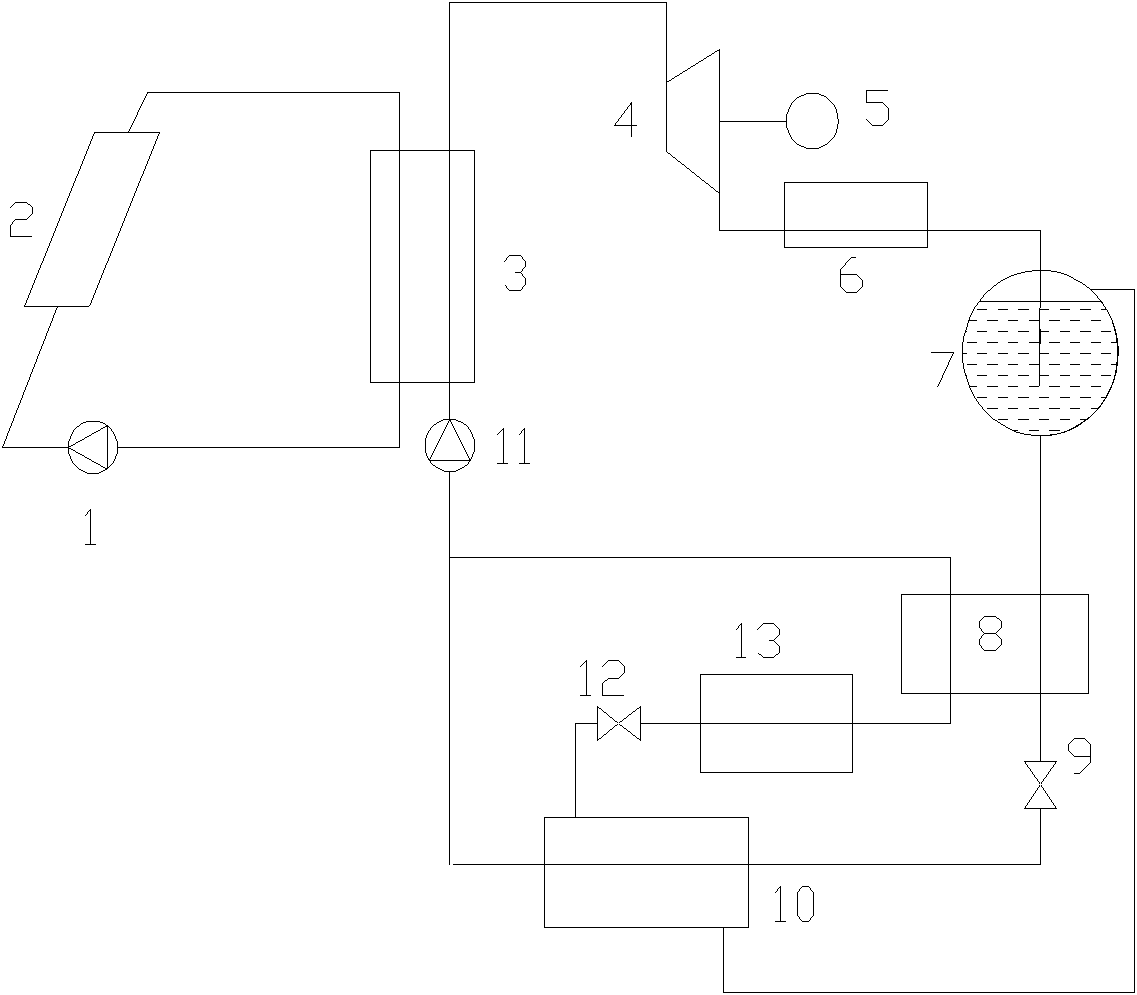
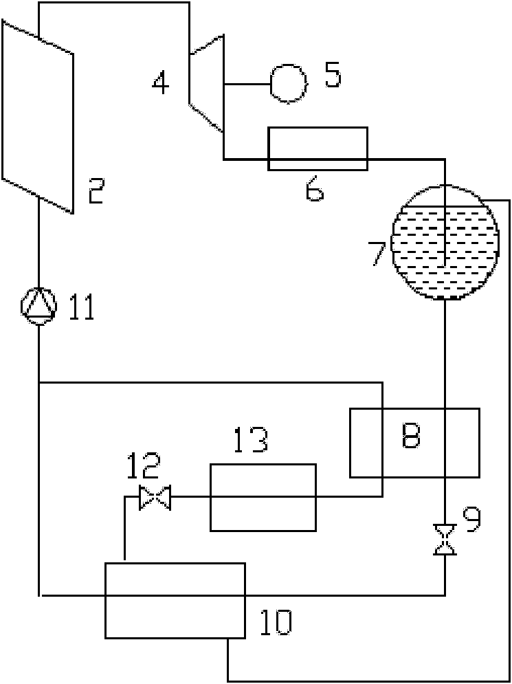
The invention discloses a solar energy-driven cogeneration device. The device mainly comprises a solar heat collecting device, a steam turbine or an expander, a generator, a condenser, a gas-liquid separator, a regenerator, a condensation evaporator, an evaporator and a working medium pump, wherein the outlet of the solar heat collecting device is connected with the steam turbine or the expander;the steam turbine or the expander is connected with an engine; the steam outlet of the steam turbine or the expander is connected with the condenser and the gas-liquid separator in turn; the liquid outlet of the gas-liquid separator is connected with the regenerator, the condensation evaporator and the working medium pump in turn; the steam outlet of the gas-liquid separator is connected with thecondensation evaporator, the evaporator, the regenerator and the working medium pump in turn; and the outlet of the working medium pump is connected with the inlet of the solar heat collecting deviceto form a cycle. By the device, the utilization rate of the collected solar energy can be greatly improved, comprehensive efficiency is improved, and the area of a heat collector can be effectively reduced.
Description
A solar-powered combined power supply device technical field The invention relates to a combined power supply device driven by solar energy. Background technique As an important energy source among renewable clean energy sources, solar energy is inexhaustible, and more and more attention has been paid to its development and utilization. Conventional use of solar energy is mainly focused on the application of domestic hot water, and more and more attention is currently being paid to solar power generation and composite utilization. Solar power generation includes photothermal power generation and photovoltaic power generation, both of which have certain application markets. In solar photothermal power generation, solar collectors are used to collect solar energy to heat the circulating working medium - heat transfer oil. Heat transfer oil has the characteristics of large heat capacity, strong heat conduction ability, and high boiling point. Compared with conventional wate...
Claims
Login to View More Application Information
Patent Timeline
 Patent Type & Authority Applications(China)
IPC IPC(8): F03G6/06F01D15/00F01K25/00
CPCY02E10/46
Inventor 张小松宋建忠
Owner SOUTHEAST UNIV
Features
- R&D
- Intellectual Property
- Life Sciences
- Materials
- Tech Scout
- Unparalleled Data Quality
- Higher Quality Content
- 60% Fewer Hallucinations
Learn More Browse by: Latest US Patents, China's latest patents, Technical Efficacy Thesaurus, Application Domain, Technology Topic, Popular Technical Reports.
© 2025 PatSnap. All rights reserved.Legal|Privacy policy|Modern Slavery Act Transparency Statement|Sitemap|About US| Contact US: help@patsnap.com


