
Coal engineering hole directional drilling method

A directional drilling and engineering technology, applied in directional drilling and other directions, can solve the problems of low drilling accuracy and complex procedures, and achieve the effects of improving drilling utilization, simple procedures and high drilling accuracy

Inactive Publication Date: 2011-06-15
BEIJING CHINA COAL MINE ENG CO LTD
View PDF4 Cites 16 Cited by
  • Summary
  • Abstract
  • Description
  • Claims
  • Application Information

AI Technical Summary

Problems solved by technology

[0003] In order to overcome the deficiencies of the existing directional drilling methods, such as low drilling precision and complicated procedures, the present invention provides a directional drilling method for engineering holes in coal mines. The directional drilling method for engineering holes in coal mines has high drilling precision, simple procedures, and The smooth hole is beneficial to the next step of drilling.

Method used


Image

  • Coal engineering hole directional drilling method
  • Coal engineering hole directional drilling method
  • Coal engineering hole directional drilling method

Examples


example 1

[0019] Example 1: Directional Drilling of No. 2 Well Group Holes in Donghuantuo Mine

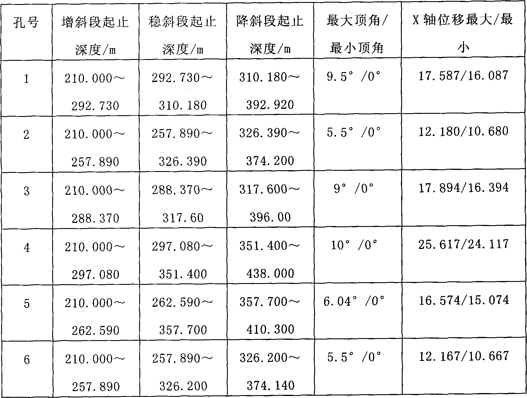
[0020] The design well depth of Donghuantuo No. 2 well of the former Kailuan Mining Bureau is 737m, the depth of the pre-grouting hole on the ground is 750m, and the shallow section below 420m adopts the freezing method, which has already met the excavation conditions. In order to shorten the construction period of the well, the lower grouting and the excavation of the upper frozen section need to be operated in parallel. Since the surrounding of the wellhead is occupied by drilling facilities, it is impossible to arrange vertical grouting holes. The opening positions of the grouting holes are all a certain distance from the wellhead, bypass the frozen section through the S hole, and enter the grouting hole design drop point range in the grouting section , Complete the grouting construction of the section deeper than 420m.

[0021] The specific steps are as follows:

[0022] 1. Design the ...

example 2

[0053] Example 2: Directional correction of grouting holes in the main shaft of Dashucun Coal Mine

[0054]The Dashucun mine of the former Fengfeng Mining Bureau has a designed annual output of 900,000 tons. The main and auxiliary shafts adopt ground pre-grouting technology for water plugging, and the three grouting holes of the auxiliary shaft use directional drilling technology for deviation correction. The depth of the grouting hole in the auxiliary shaft is 703.5m, and the deviation rate is required to be no more than 10‰. When the deviation rate of the grouting hole is close to 10‰, the deviation will be corrected to meet the requirements of verticality and basically uniform distribution of landing points.

[0055] 1. Design the trajectory of the grouting hole

[0056] Because the grouting hole is required to be a straight hole, the purpose of directional drilling is to correct the deviation, so no trajectory design is required.

[0057] 2. The main equipment, instrument...


PUM


Abstract

The invention provides a coal engineering hole directional drilling method, which mainly solves the problems of low drilling precision and complex procedure of the conventional directional drilling method. The directional drilling method is characterized by comprising the following steps of: 1, designing a drilling trace: designing the drilling trace and drilling parameters according to the requirement of engineering drilling; 2, determining special equipment, machines and devices which are required by the engineering, and combining the drilling equipment according to the requirements of all drilling stages; 3, constructing according to the trace and the parameters which are designed in the step 1, measuring the finished drilling trace by using an inclinometer after one stage is finished, analyzing whether data is the same as the designed trace, and expecting the next trace tendency; and 4, performing error correction design if error correction is needed to be performed in the step 3, repeating the content in the step 2, and cycling until the drilling is finished; and if error correction is not needed in the step 3, continuing to drill the next hole section until the drilling is finished. The coal engineering hole directional drilling method has the characteristics of high drilling precision, simple procedure, smooth drilled holes and contribution to the next work of drilling.

Description

Technical field: [0001] The invention relates to a method in the field of drilling engineering construction, in particular to a directional drilling method for coal mine engineering holes. Background technique: [0002] Drilling engineering can be divided into three categories according to its application fields: one is the field of exploration (EXPLORATION), which mainly focuses on exploration, and refers to the purposeful exploration of underground or seabed geological structures including scientific drilling (continental and marine scientific drilling). , changes in crustal activity, various minerals, energy and groundwater resources, etc.; the second is the field of production, which focuses on production, including various production wells, observation wells, oil and gas exploitation, geothermal, groundwater, salt minerals and Other minerals, sewage treatment, earthquake observation, land subsidence and groundwater pollution; the third is the construction (CONSTRUCTION)...

Claims


Application Information

Patent Timeline
Patent Type & Authority Applications(China)
IPC IPC(8): E21B7/04
Inventor 韩圣铭周兴旺刘敏郑军左永江王胜利徐润赵宏伟王铁群
Owner BEIJING CHINA COAL MINE ENG CO LTD
Learn More