Assembled monolithic concrete ribbed hollow floor slab
A technology of hollow floor slab and concrete, which is applied in the field of floor slabs to achieve the effects of reducing project cost, reducing structure height and saving materials
Inactive Publication Date: 2011-06-15
辛崇安
View PDF3 Cites 5 Cited by
- Summary
- Abstract
- Description
- Claims
- Application Information
AI Technical Summary
Problems solved by technology
There is no precedent for prefabricated internal formwork components used in ribbed hollow-core slabs at this stage in China
In addition, in the field of densely ribbed slabs, there is no precedent for adopting lattice reinforcement technology measures in the integrated measures of strengthening the combination of prefabrication and cast-in-place
Method used
View moreImage
Smart ImageViewing Examples
Examples
Embodiment Construction
Login to View More PUM
 Abstract
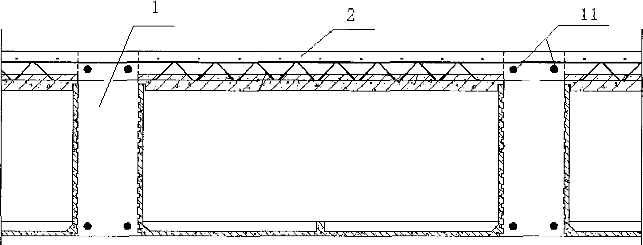
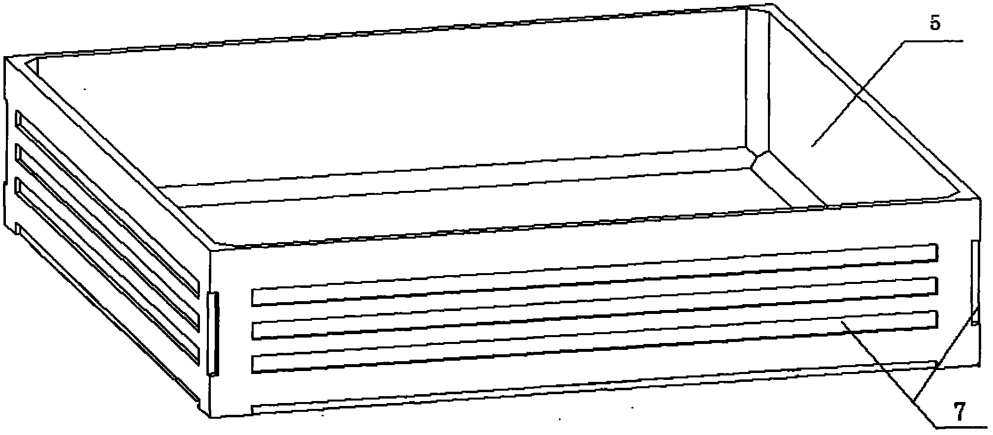
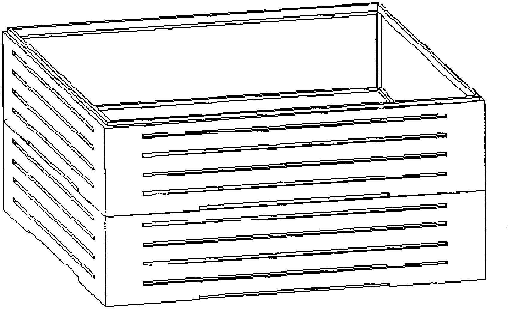
The invention relates to a floor slab, in particular to an assembled monolithic concrete ribbed hollow floor slab with combination of prefabrication and casting in place and joint stress, which comprises reinforced concrete rib beams (1), a reinforced concrete overlapping layer (2) and assembled box dies (3); each reinforced concrete rib beam is formed by casting in place between the adjacent assembled box dies; the reinforced concrete overlapping layer is formed by casting in place above the assembled box dies; each assembled box die (3) comprises a lattice reinforced composite slab (4) and an open box (5), and each lattice reinforced composite slab is a top slab of the open box (5); and protruding steel bars (6) are arranged in the lattice reinforced composite slabs (4), the protruding steel bars protrude into the peripheral rib beams for anchoring, longitudinal stressed steel bars (11) in the rib beams are hooked, and the rib beams (1) and the lattice reinforced composite slabs (4) are jointly stressed. The structural height of the floor slab can be greatly reduced, and higher using space for a building can be provided under the situation of same storey height.
Description
An Assembled Integral Concrete Rib Hollow Floor Slab technical field The invention relates to a floor slab, in particular to an assembled integral concrete dense-ribbed hollow-core floor slab combining prefabrication and cast-in-place under common stress. Background technique With the rapid development of my country's economic construction, reinforced concrete structures have been widely used in industrial and civil buildings, and have achieved good technical and economic results. Due to the requirements of high-rise, large space and earthquake resistance in buildings, many new structural systems with good technical and economic effects have been developed in recent years. In the past ten years, concrete ribbed hollow-core slabs have been widely used in construction projects in my country. Ribbed hollow-core floor slab refers to 1. The one-way or two-way type with rib spacing <= 1.5m is called dense-ribbed hollow-core floor slab; 2. It is suitable for public buildings...
Claims
Login to View More Application Information
Patent Timeline
 Patent Type & Authority Applications(China)
IPC IPC(8): E04B5/17E04B5/18E04G15/06
Inventor 辛崇安
Owner 辛崇安
Features
- R&D
- Intellectual Property
- Life Sciences
- Materials
- Tech Scout
- Unparalleled Data Quality
- Higher Quality Content
- 60% Fewer Hallucinations
Learn More Browse by: Latest US Patents, China's latest patents, Technical Efficacy Thesaurus, Application Domain, Technology Topic, Popular Technical Reports.
© 2025 PatSnap. All rights reserved.Legal|Privacy policy|Modern Slavery Act Transparency Statement|Sitemap|About US| Contact US: help@patsnap.com


