
Through-tunnel lower pilot girder type non-moving lifting bridge girder erection machine

A technology of bridge hanger and tunnel crossing, which is applied in the direction of bridges, bridge construction, erection/assembly of bridges, etc., can solve the problem of inability to achieve short-distance beam erection.

Inactive Publication Date: 2011-06-15
徐州徐工铁路装备有限公司
View PDF9 Cites 7 Cited by
  • Summary
  • Abstract
  • Description
  • Claims
  • Application Information

AI Technical Summary

Problems solved by technology

[0006] The purpose of the present invention is to provide a fixed-point hoisting bridge erecting machine with a lower guide beam for passing through the tunnel, which solves the problem that the whole machine is super high and super wide, and must be disassembled to be transported through the tunnel by a beam transport vehicle; distance beam problem

Method used


Image

  • Through-tunnel lower pilot girder type non-moving lifting bridge girder erection machine
  • Through-tunnel lower pilot girder type non-moving lifting bridge girder erection machine
  • Through-tunnel lower pilot girder type non-moving lifting bridge girder erection machine

Examples


Embodiment 1

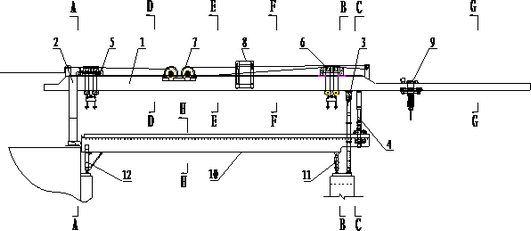
[0035] Embodiment 1: The lifting bridge erecting machine includes a beam erecting machine and a lower guiding beam machine; the beam erecting machine includes a main beam 1, an O-shaped rear outrigger 2, a foldable front outrigger 3, an auxiliary outrigger 4, and a front hanger Beam crane 5, rear crane beam crane 6, winch assembly 7, guide beam crane 8, guide beam passing crane 9, lower guide beam main beam 10 guide beam front outrigger 11 and guide beam rear outrigger 12 A foldable front outrigger 3 and an auxiliary outrigger 4 are connected to the bottom surface of the front part of the main beam 1, and an O-shaped rear outrigger 2 is connected to the rear end of the main beam; Hanging beam crane 6, winch assembly 7 is installed in the middle of the main beam, guide beam crane 8 and guide beam passing crane 9 are connected on the track on the upper end surface of main beam 1, guide beam passing crane 9 is located on the main beam 1 front end; the lower guide beam machine inc...


PUM


Abstract

The invention relates to a through-tunnel lower pilot girder type non-moving lifting bridge girder erection machine which belongs to the field of railway bridge erection equipment. A folding front support leg and an auxiliary support leg are connected on the bottom surface at the front part of a main girder of the lifting bridge girder erection machine, and the rear end of the main girder is connected with an O-shaped rear support leg; a front lifting girder overhead crane and a rear lifting girder overhead crane are arranged on the main girder, a hoisting component is mounted at the middle part of the main girder, a pilot girder lifting machine and a pilot girder through-hole overhead crane are connected on a track on the upper end surface of the main girder, and the pilot girder through-hole overhead crane is positioned at the front end of the main girder; and a lower pilot girder machine comprises a pilot girder front support leg and a pilot girder rear support leg of the main girder of a lower pilot girder, and the pilot girder front support leg and the pilot girder rear support leg are arranged at the front end part and the rear end part of the main girder of the lower pilot girder. The through-tunnel lower pilot girder type non-moving lifting bridge girder erection machine has the advantages that the packing through-tunnel state of the through-tunnel lower pilot girder type non-moving lifting bridge girder erection machine is the pilot girder front-mounted type state, and the pilot girder machine can be in place when going out of a tunnel, thereby greatly improving the erection efficiency for resetting the whole machine after going out of the tunnel, being good in adaptability to working conditions, saving construction time, saving construction cost, and being smooth, safe and reliable.

Description

technical field [0001] The invention relates to a railway bridge erecting device, in particular to a tunnel-passing lower guide beam type fixed-point lifting bridge erecting machine. Background technique [0002] The construction equipment for the erection of high-speed railway bridges is the bridge erecting machine, which is divided into the integrated machine for transporting the frame and the split type bridge erecting machine for the transport frame. It is a towed non-fixed point lifting bridge erecting machine and a lower guide beam type fixed point lifting bridge erecting machine. Although the all-in-one machine can pass through the tunnel, its efficiency is extremely low because the working conditions of beam transport and beam erection cannot be carried out at the same time, and it is not suitable for long-distance erection requirements. The drag-type non-fixed-point bridge erecting machine is dragged forward by the steel wire rope of the front crane during the beam...

Claims


Application Information

Patent Timeline
IPC IPC(8): E01D21/06
Inventor 王磊张洪涛崔万成郑晓雯程红威乔彬徐小雪张强刘西超姜军
Owner 徐州徐工铁路装备有限公司
Learn More