Catalytic cracking method with maximisation of diesel bases

A base oil, catalytic cracking technology, used in catalytic cracking, chemical instruments and methods, catalyst regeneration/reactivation, etc., can solve the problems of reduced catalyst activity, low specific surface area, low yield, etc.

Inactive Publication Date: 2015-07-01
TOTAL RAFFINAGE MARKETING
View PDF4 Cites 0 Cited by
  • Summary
  • Abstract
  • Description
  • Claims
  • Application Information

AI Technical Summary

Problems solved by technology

[0008] - to have a medium or low specific surface area (for example below 110m 2 / g) low activity catalysts are circulated in the plant to favor the bottom conversion of the heaviest components of the feedstock and limit the conversion of the feedstock, but the yields of dry gas and liquefied gas or LPG are too low (typically less than 15%),
[0009] - Or use commercially available acidic catalysts such as those currently used to maximize gasoline production, altering the effective surface area of ​​the catalyst by coking to limit its conversion by making the catalyst less active before introducing fresh feedstock into the reactor

Method used


Image

  • Catalytic cracking method with maximisation of diesel bases
  • Catalytic cracking method with maximisation of diesel bases
  • Catalytic cracking method with maximisation of diesel bases

Examples


Embodiment 1

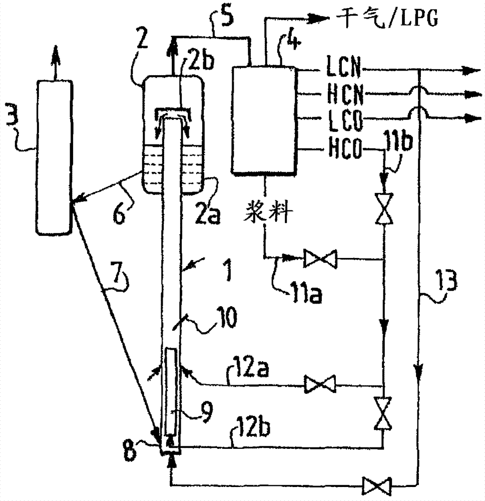
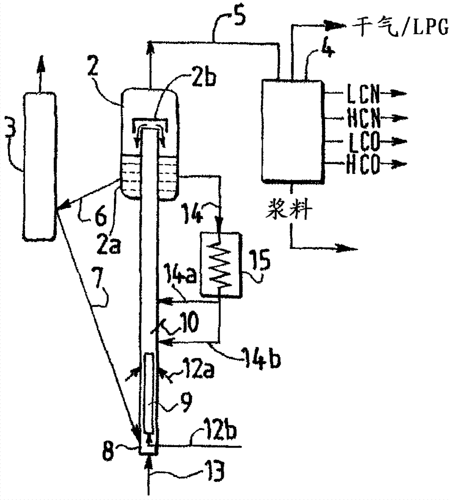
[0072] This example shows the results obtained between a conventional catalytic cracking unit operating in a gasoline-maximizing mode and a catalytic cracking or FCC unit modified according to the invention with one or two upflow reactors operating in a distillate-maximizing mode. Comparing results.

[0073] This corresponds to a modification of an existing FCC plant that processes pre-hydrotreated vacuum distillate feedstock and uses a common acidic catalyst (product from Albemarle) where the ratio of micropore specific surface to mesopore specific surface is equal to two.

[0074] To increase distillate production while minimizing light gasoline production, the operating conditions of the FCC and the cutting point of the effluent produced in the primary fractionation were varied. The catalyst remains the same regardless of equipment configuration and operating conditions. Two operations of a device having a configuration (X1 and X2) corresponding to the features of the inve...

Embodiment 2

[0086] Based on the results obtained on the test plant, this example shows different sets of yields that can be obtained for a feedstock consisting exclusively of atmospheric residue at operating conditions and the use of catalyst recycled from the separator and the recycle of the unconverted fraction as function obtained.

[0087] The catalyst is a conventional catalyst used for the production of gasoline from heavy atmospheric residue type feedstock (the ratio of micropore specific surface to mesopore specific surface is equal to 1, total surface area = 110m 2 / g, Ni = 3000 ppm by weight and V = 5000 ppm by weight). The raw material is atmospheric residual oil with a boiling point of 330-730°C and a density of 928.9kg / m 3 , Conradson (Comradson) carbon residue is 3.9% by weight.

[0088] In this example, Example 1 corresponds to the gasoline operating mode, which favors the production of light and heavy gasoline and liquefied gas (LPG). This is the reference ratio for this...

Embodiment 3

[0096] This example illustrates the advantages of the present invention using conventional cracking catalysts, which are beneficial for gasoline production due to the high microporous (even zeolite) specific surface, which is characterized in Compared with shaped catalysts (commercially known as BCA (bottom cracking additive)), the ratio of micropore specific surface to mesopore specific surface is usually above 2, which is beneficial to the production of LCO under the same cracking conditions claimed in the present invention But it is not good for the slurry.

[0097] The operating conditions (TRX or temperature and C / O) are given in Table IV below. As previously described in Example 2, 3 runs were performed using a zeolite catalyst and 2 additional runs used a BCA catalyst known to preferentially form LCO-type distillates.

[0098] E1 corresponds to plant operation in gasoline mode on a zeolite catalyst.

[0099] D1 corresponds to plant operation in distillate mode on zeol...


PUM

PropertyMeasurementUnit
boiling pointaaaaaaaaaa

Abstract

The catalytic cracking process comprises performing a cracking reaction in a bottom fluidized bed reactor (1), separating cracked hydrocarbons and catalyst coke, and fractionating the cracked hydrocarbons and a then regenerating the catalyst coke. The hydrocarbon feedstock is injected into an upstream reactor of a partially deactivated catalyst by coking so that the temperature of reaction of the effluent ranges from 470-600[deg] C. The pre-coking of the catalyst is achieved by injecting a hydrocarbon compound having a boiling temperature of 350[deg] C on a portion of regenerated catalyst. The catalytic cracking process comprises performing a cracking reaction in a bottom fluidized bed reactor (1), separating cracked hydrocarbons and catalyst coke, and fractionating the cracked hydrocarbons and a then regenerating the catalyst coke. The hydrocarbon feedstock is injected into an upstream reactor of a partially deactivated catalyst by coking so that the temperature of reaction of the effluent in outlet of the reactor ranges from 470-600[deg] C. The pre-coking of the catalyst in the reactor is achieved by injecting a hydrocarbon compound having a boiling temperature of 350[deg] C on a portion of regenerated catalyst, where the portion is defined by an area defined by an internal device. A part of the separated catalyst coke is returned directly to the reactor in downstream of the injection of hydrocarbon feedstock at a temperature below the reaction temperature. A part of the regenerated catalyst is coked in upstream of the injection of the load by the hydrocarbon compound, and a portion (1-75%) of the stripped and recovered catalyst coke is returned in upstream and / or downstream of the injection of load into the reactor. A cut-off temperature of lower than 160[deg] C is provided on the catalyst regenerated in the reactor, during injection step. The process further comprises performing additional cracking reaction in the reactor and recycling the hydrocarbonized cut having a boiling point of lower than 145[deg] C and / or a boiling point of greater than 350[deg] C. A second upstream reactor is used for cracking of hydrocarbon cuts with a ratio of carbon and oxygen of 4-20 at 470-650[deg] C. An independent claim is included for a device performing for catalytic cracking process to maximize production of diesel oils.

Description

technical field [0001] The present invention relates to a catalytic cracking process for maximizing the production of diesel base stocks, comprising a cracking reaction step in at least one upflow fluidized bed reactor, a step of separating cracked hydrocarbons and catalyst, a step of fractionating cracked hydrocarbons and coking Catalyst regeneration steps. The invention also relates to a plant for carrying out said process, which plant may comprise one or more upflow reactors. Background technique [0002] In recent years, refineries and companies offering FCC (Fluid Catalytic Cracking) technology licenses have worked to optimize the operation of these processes and corresponding equipment. The optimization is initially focused on the production of light liquefied gas products (or LPG: Liquefied Petroleum Gas), naphtha and gasoline, which basically meet the market for polymers produced by the polymerization of light olefins or for light and heavy motor vehicles Most of t...

Claims


Application Information

Patent Timeline
Patent Type & Authority Patents(China)
IPC IPC(8): C10G55/06
CPCB01J8/34C10G2400/04C10G2300/4081C10G2300/1011C10G2300/4093C10G11/18C10G2300/301B01J38/30B01J29/90C10G2300/708Y02P30/20
Inventor 马克·博列斯帕特里克·勒罗伊迈克尔·埃沙尔蒂埃里·戈捷
Owner TOTAL RAFFINAGE MARKETING
Why Eureka
Try Eureka