
Three-dimensional mixer and three-dimensional mixing method

A mixing machine, three-dimensional technology, applied in the direction of mixers, chemical instruments and methods, mixers with rotating containers, etc., can solve the problems of reduced service life of the main shaft, inapplicability, and far away rotation center of gravity, etc., to achieve mixing effect and Efficiency improvement, convenient hoisting and disassembly, and easy processing to achieve the effect

Inactive Publication Date: 2011-06-15
BEIJING ZHONG KE SAN HUAN HI TECH +1
View PDF2 Cites 12 Cited by
  • Summary
  • Abstract
  • Description
  • Claims
  • Application Information

AI Technical Summary

Problems solved by technology

[0002] The existing micro-powder mixers are single-axis structures, the mixing effect is poor, the material tank is not easy to hoist and fix at a certain angle, the operability of the equipment is not strong, and the overall rotation center of gravity is far away from the axis center, which makes the main shaft The service life is greatly reduced
[0003] Chinese patent application No.200610134771.5 discloses a high-speed mixer, which adopts a built-in rotating shaft and a stirring rod. Although the mixing speed is fast, it is difficult for some powders that need to be isolated from the air (powders that are easy to oxidize with low oxygen content) inapplicable
[0004] Chinese patent application No.93231770.7 discloses a high-efficiency vacuum feed mixer, the tank and the mixer are integrated, the material to be mixed needs to be transferred into the V-shaped tank, and then transferred out after mixing. The operation process It is cumbersome and not conducive to ensuring the isolation of materials and air

Method used


Image

  • Three-dimensional mixer and three-dimensional mixing method
  • Three-dimensional mixer and three-dimensional mixing method

Examples


Embodiment Construction

[0012] The specific structure and operation process of the present invention will be described below with reference to the accompanying drawings.

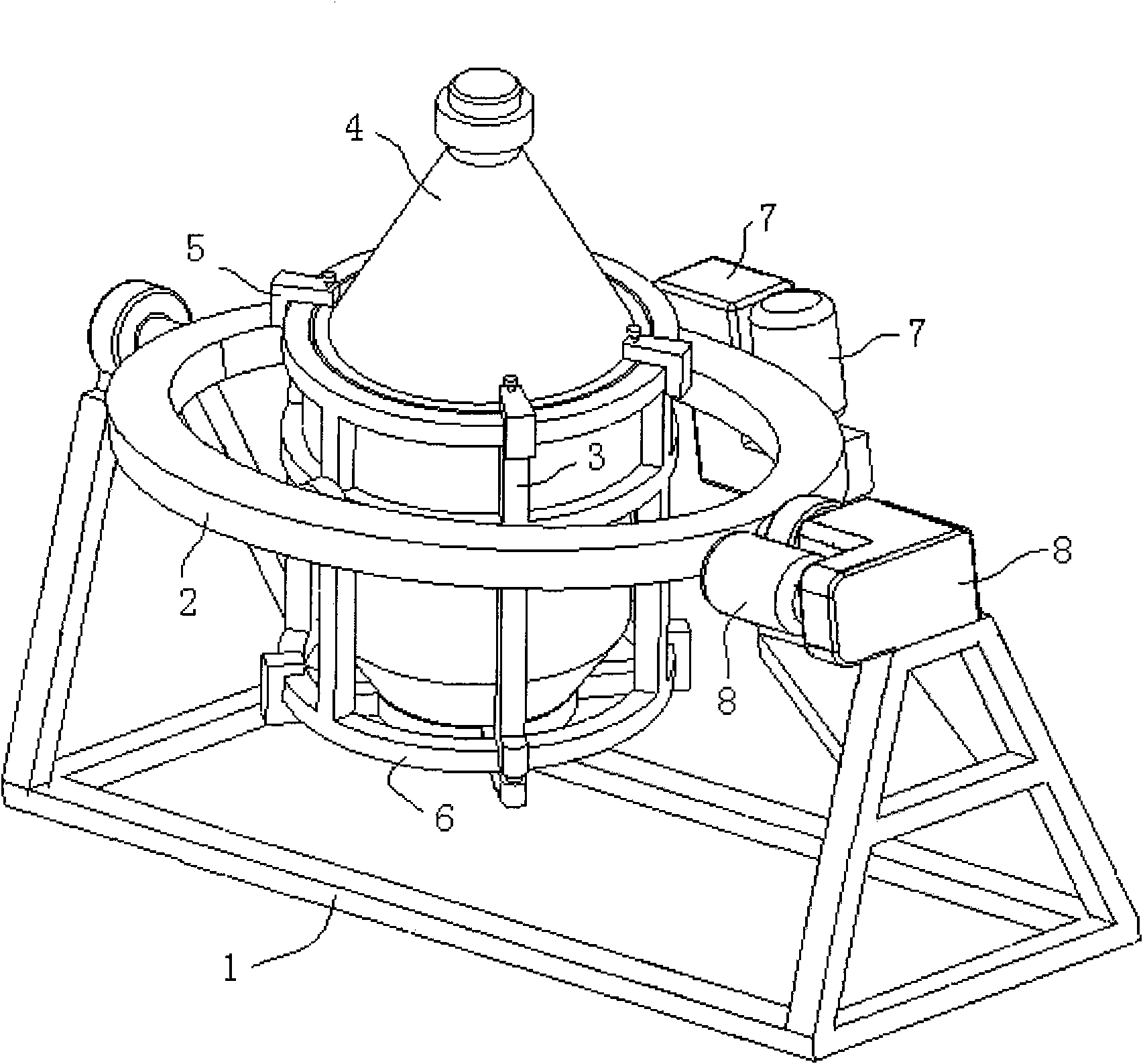
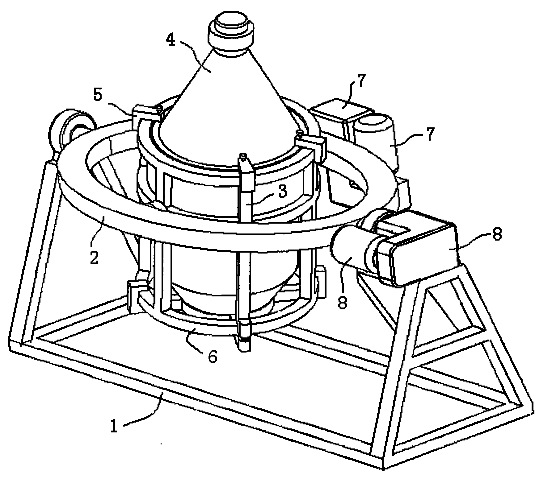
[0013] The three-dimensional mixing machine according to the present invention is mainly composed of: main body support 1; main rotating body 2; auxiliary rotating body 3; mixing tank 4; ; The main rotating body gear box and motor 8 components.

[0014] The connection mode between each part: the main body bracket 1 and the main rotating body 2 are connected by bearings; the main rotating body 2 and the auxiliary rotating body 3 are also connected by bearings; the mixing tank 4 is connected by the upper clamp 5 and the bottom clamp 6 They work together and are fixed on the entire frame, and the upper clamp 5 and the bottom clamp 6 are fixed on the auxiliary rotating body 3 through the pin structure; the auxiliary rotating body reduction box and the motor 7 are fixed on the main rotating body 2, but the deceleration The torque of th...


PUM


Abstract

The invention relates to a three-dimensional mixer, which is characterized by comprising a main body bracket, a main rotating body, an auxiliary rotating body, an upper port clamp and a supporting bottom lamp of a mixing tank, a reduction gearbox and a motor for the auxiliary rotating body, and a reduction gearbox and a motor for the main rotating body, wherein the main body bracket is connected with the main rotating body capable of rotating around a first horizontal shaft by a bearing; the main rotating body is also connected with the auxiliary rotating body capable of rotating around a second horizontal shaft by a bearing; the second horizontal shaft is vertical to the first horizontal shaft; the mixing tank is fixed on a frame by the upper port clamp and the supporting bottom clamp; the upper port clamp and the supporting bottom clamp are fixed on the auxiliary rotating body through pin structures; the reduction gearbox and the motor for the auxiliary rotating body are fixed on the main rotating body and a torque of the reduction gearbox of the auxiliary rotating body is transmitted to the auxiliary rotating body; and the reduction gearbox and the motor for the main rotating body are fixed on the main body bracket. According to the three-dimensional mixer, the mixing efficiency and the mixing effect are greatly improved, and equipment is easier to operate and has longer service life.

Description

technical field [0001] The invention relates to a three-dimensional mixing machine and a three-dimensional mixing method, in particular to a powdery solid mixing device and method, which are used for mixing a large amount of powder. technical background [0002] The existing micro-powder mixers are single-axis structures, the mixing effect is poor, the material tank is not easy to hoist and fix at a certain angle, the operability of the equipment is not strong, and the overall rotation center of gravity is far away from the axis center, which makes the main shaft The service life is greatly reduced. [0003] Chinese patent application No.200610134771.5 discloses a high-speed mixer, which adopts a built-in rotating shaft and a stirring rod. Although the mixing speed is fast, it is difficult for some powders that need to be isolated from the air (powders that are easy to oxidize with low oxygen content) not suitable. [0004] Chinese patent application No.93231770.7 disclose...

Claims


Application Information

Patent Timeline
Patent Type & Authority Applications(China)
IPC IPC(8): B01F9/00
Inventor 房栋
Owner BEIJING ZHONG KE SAN HUAN HI TECH
Learn More