Resource distribution method and device for multi-relay orthogonal frequency division multiplexing system
A technology of resource allocation and orthogonal frequency division, applied in the field of wireless network communication, to achieve the effect of improving transmission rate and optimizing system performance
- Summary
- Abstract
- Description
- Claims
- Application Information
AI Technical Summary
Problems solved by technology
Method used
Image
Examples
Embodiment 1
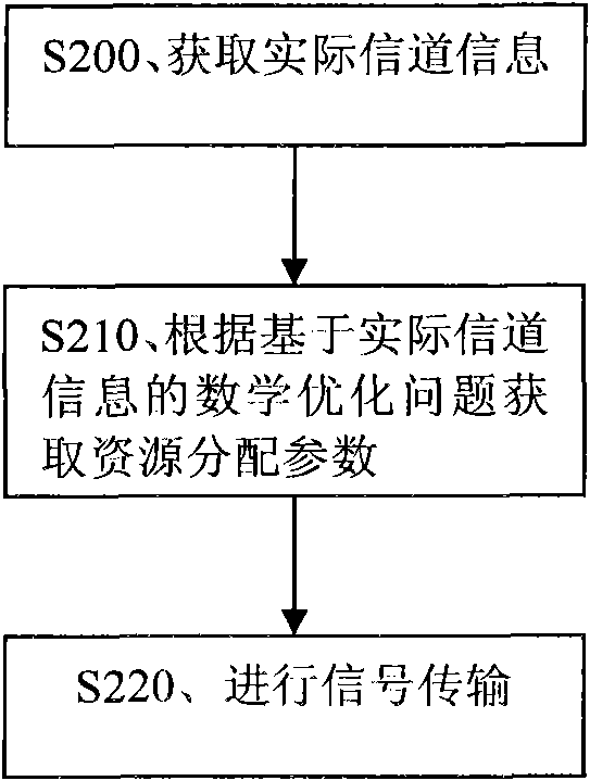
[0036] Embodiment 1, a resource allocation method. The flow of the method is attached figure 2 shown.
[0037] figure 2 In S200, acquire actual channel information. The actual channel information here may be the equivalent channel gain of each subcarrier.
[0038] The process of obtaining the actual channel information may be: first obtain the channel coefficient of each subcarrier, and then calculate the equivalent channel gain of each subcarrier by using the channel coefficient of each subcarrier.
[0039] S210. Acquire resource allocation parameters according to a mathematical optimization problem based on actual channel information. The resource allocation parameters here include: at least two of subcarrier power allocation, relay selection and subcarrier pairing. The mathematical optimization problem here is to use the end-to-end transmission rate optimization principle based on channel information for subcarrier power allocation and relay selection. Mathematical o...
Embodiment 2
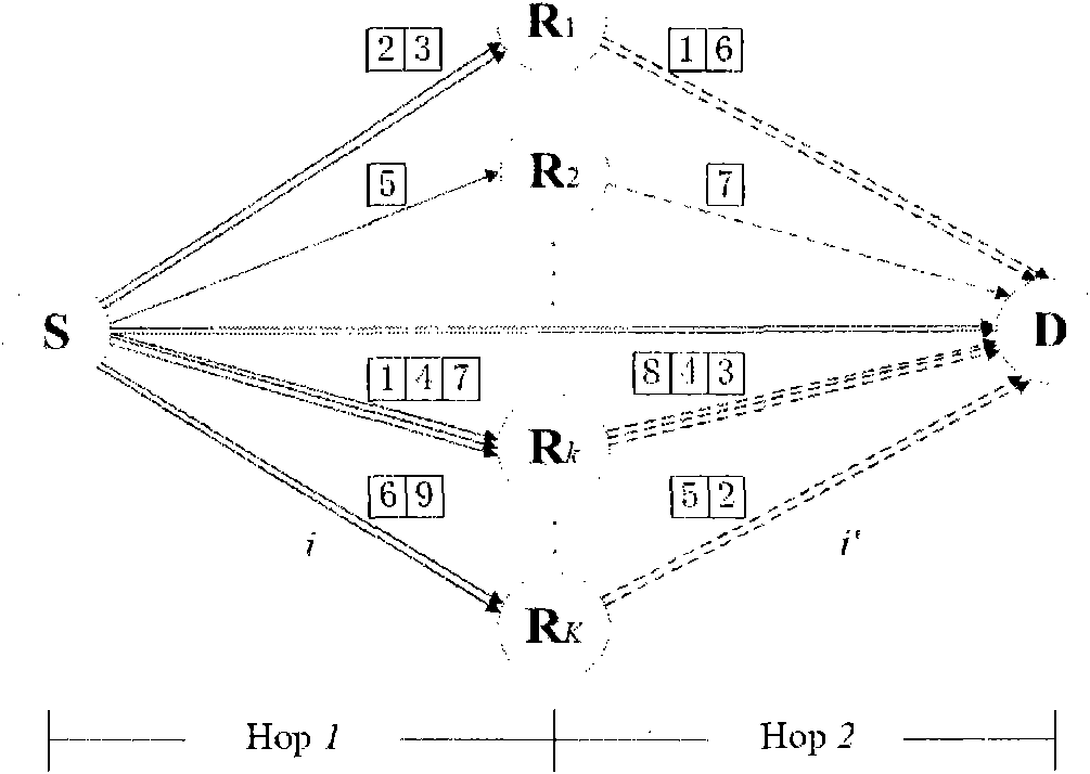
[0086] Embodiment 2, resource allocation method. This method is applicable to the OFDM system including the relay network as attached image 3 As shown, the flow of the method is as attached Figure 4 shown.
[0087] image 3 A two-hop multi-relay cooperative OFDM system based on the amplify-and-forward AF protocol is shown. The OFDM system includes: a source node S, K relay nodes namely R 1 to R K and a target node D. The source node S communicates with the destination node D based on OFDM through K relay nodes.
[0088] exist image 3 Among them, there are K channels between the source node S and K relay nodes, there is one channel between the source node S and the destination node D, and there are K channels between the K relay nodes and the destination node D. Therefore, image 3 There are 2K+1 channels in , and it can be set that 2K+1 channels have the same bandwidth, and each channel experiences independent frequency selective fading. Each channel is logically d...
Embodiment 3
[0155] Embodiment 3, resource allocation method. This method is a resource allocation method under the condition that each subcarrier power is allocated equally, that is, a resource allocation method based on equal subcarrier power allocation. The flow of the method is attached Figure 5 shown.
[0156] Figure 5 In S500, acquire actual channel information, that is, acquire channel information of all subcarriers.
[0157] The channel information obtained in S500 is: the equivalent channel gain of each sub-carrier obtained through channel coefficient calculation. The equivalent channel gain of each subcarrier may include: the equivalent channel gain of the subcarrier i between the source node S and the relay node k, that is, the equivalent channel gain α of the first hop subcarrier i i,k,1 , The equivalent channel gain of the subcarrier i between the relay node k and the target node D is the equivalent channel gain α of the second hop subcarrier i i,k,2 , and the equivalent ...
PUM
 Abstract
Description
Claims
Application Information
 - R&D Engineer
- R&D Manager
- IP Professional
- Industry Leading Data Capabilities
- Powerful AI technology
- Patent DNA Extraction
Browse by: Latest US Patents, China's latest patents, Technical Efficacy Thesaurus, Application Domain, Technology Topic, Popular Technical Reports.
© 2024 PatSnap. All rights reserved.Legal|Privacy policy|Modern Slavery Act Transparency Statement|Sitemap|About US| Contact US: help@patsnap.com


