
Electric servo control push rod

A technology of electric servo and push rod, which is applied in the direction of transmission, belt/chain/gear, mechanical equipment, etc., and can solve the problems of high cost, complex structure of electro-hydraulic push rod, and low precision of output force control

Inactive Publication Date: 2011-06-01
JILIN UNIV
View PDF3 Cites 10 Cited by
  • Summary
  • Abstract
  • Description
  • Claims
  • Application Information

AI Technical Summary

Problems solved by technology

[0003] The purpose of the present invention is to provide an electric servo control push rod that is suitable for precise control of output force and hydraulic pressure output, and overcomes the low control accuracy of the output force of the electric push rod and the complicated structure of the electrohydraulic push rod in the past. high deficiency

Method used


Image

  • Electric servo control push rod
  • Electric servo control push rod
  • Electric servo control push rod

Examples


Embodiment Construction

[0016] Below in conjunction with accompanying drawing and specific embodiment the present invention will be described in further detail:

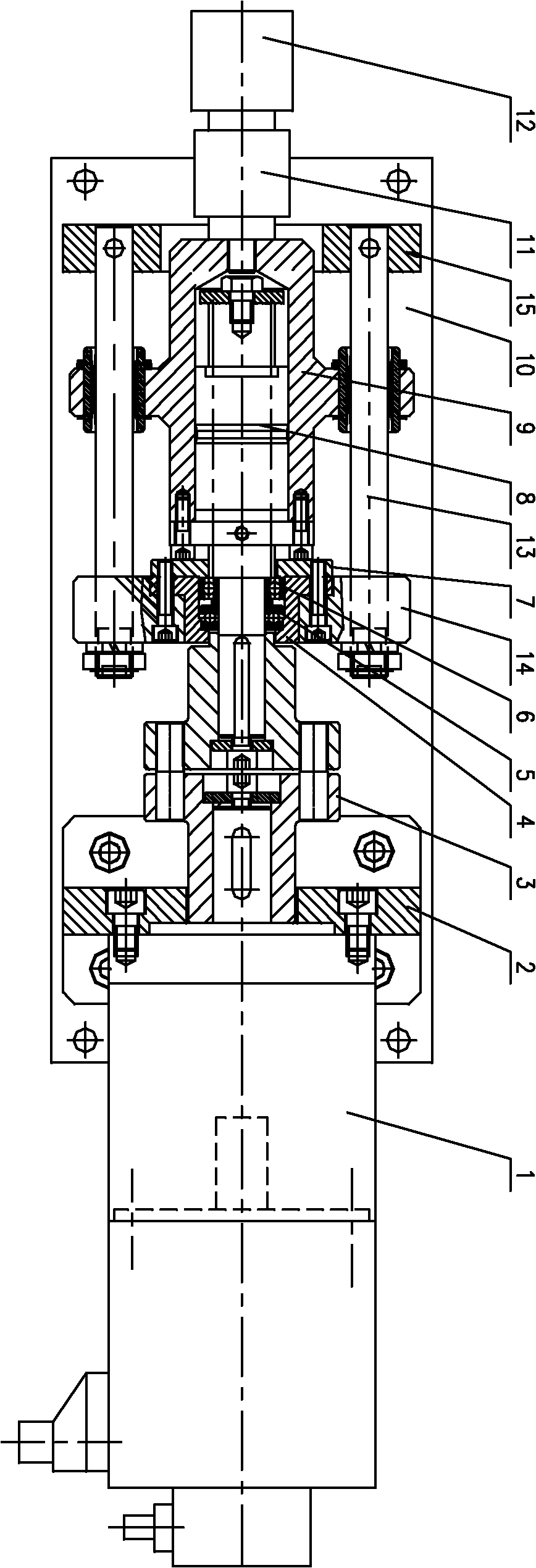
[0017] An electric servo control push rod, consisting of a base 10, a servo motor 1, a coupling 3, a ball screw pair 8, a screw seat 9, a bearing 5, a bearing 6, a force sensor 11, a loading rod 12, and a guide post 13 . The described electric servo control push rod is composed as follows: the servo motor 1 is fixed on the right end face of the front vertical plate 2 of the base 10, and is connected with the ball screw pair 8 through the shaft coupling 3, and the ball screw pair The screw shaft of 8 is rotationally connected with the inner hole of the neutral plate 14 of the base 10 through the thrust bearing 5, the ball bearing 6, the cover cup 4, the gland 7, and the nut of the ball screw pair 8 is connected with the screw seat 9 through screws, A force sensor 11 and a loading rod 12 are installed at the front end of the screw seat 9 . ...


PUM


Abstract

The invention belongs to an electric push rod, and in particular relates to an electric servo control push rod which comprises a base, a motor, a coupler, a ball screw assembly, a screw base and a guide pillar, wherein the motor is a servo motor (1) which is fixedly arranged on the base (1) and connected with a screw shaft of the ball screw assembly (8) through the coupler (3), the ball screw assembly is rotatably connected with an inner hole of a vertical plate (14) of the base (10), a nut of the ball screw assembly (8) is connected with the screw base (9) through a bolt, the screw base (9) is sleeved on the guide pillar (13) and can move front and back along the guide pillar (13), and the front end of the screw base (9) is also provided with a loading feedback device. Pressure sensors (18) arranged on the servo motor 1 and a force sensor 11 or an oil cylinder output pipeline form closed loop feedback, thus the accurate force output or liquid pressure output is realized. The invention has the advantages of simple structure and high efficiency, and is suitable for various occasions.

Description

technical field [0001] The invention belongs to an electric push rod, in particular to an electric servo-controlled push rod. Background technique [0002] In the past, electric push rods were mostly composed of ordinary motors, reduction gears, screws, nuts, push rods, etc., and most of them were force output types. Its output force control precision is low. The electro-hydraulic push rod requires an additional hydraulic station. In order to control accurate force output, special pressure control components need to be installed. Such as proportional valves or servo valves, the structure is complex and the cost is high. Contents of the invention [0003] The purpose of the present invention is to provide an electric servo control push rod that is suitable for precise control of output force and hydraulic pressure output, and overcomes the low control accuracy of the output force of the electric push rod and the complicated structure of the electrohydraulic push rod in th...

Claims


Application Information

Patent Timeline
IPC IPC(8): F16H25/22F16H35/00
Inventor 赵小楼王立宁刘学峰刘大欣
Owner JILIN UNIV
Learn More