
Alternative-current/direct-current (AC/DC) dual-purpose motor control system

A dual-purpose AC and DC motor control technology, which is applied in control systems, motor control, motor generators/starters, etc., can solve the problems of large space occupation, electromagnetic interference, and many wiring, so as to improve the service life and eliminate switches. Arcs and sparks, volume reduction effect

Inactive Publication Date: 2011-05-25
SHANGHAI MARITIME UNIVERSITY
View PDF4 Cites 22 Cited by
  • Summary
  • Abstract
  • Description
  • Claims
  • Application Information

AI Technical Summary

Problems solved by technology

[0003] At present, the AC and DC dual-purpose motor usually uses a relay logic circuit composed of relays and contactors to realize the control of starting, braking, forward and reverse, etc. The control system has a complex structure, more wiring, and takes up a lot of space. Large arcs and electric sparks will be generated when switching, the electromagnetic interference is serious, and the life is greatly restricted by the life of the relay contacts
Moreover, the relay control method can only complete simple switch control, and it is difficult to realize complex functions such as motor soft start and stepless speed regulation, making it difficult to further expand the application range of AC and DC dual-purpose motors

Method used


Image

  • Alternative-current/direct-current (AC/DC) dual-purpose motor control system
  • Alternative-current/direct-current (AC/DC) dual-purpose motor control system
  • Alternative-current/direct-current (AC/DC) dual-purpose motor control system

Examples


Embodiment Construction

[0024] In order to make the technical means, creative features, goals and effects achieved by the present invention easy to understand, the present invention will be further described below in conjunction with specific illustrations.

[0025] The present invention uses power electronic devices as the main body to form the main circuit of the AC and DC dual-purpose motor control system. Through the on-off control of different power electronic switches in the main circuit, the topological structure of the main circuit can be dynamically changed according to the different working states of the motor. DC motor control.

[0026] The control of AC and DC motors includes rotation direction (forward and reverse) control, braking control and speed control. The braking of the AC / DC dual-purpose motor used in the servo application in the action mechanism generally adopts the energy consumption braking method, so this control system is designed as the energy consumption braking method.

...


PUM


Abstract

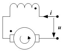
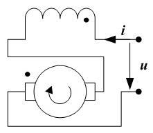
The invention discloses an alternative-current / direct-current (AC / DC) dual-purpose motor control system, which is characterized in that: an electric power electronic part Insulated Gate Bipolar Transistor (IGBT) is adopted as a non-contact controllable switch to form a control main circuit, a digital microprocessor is adopted as a control core to form a micro-controller-based AC / DC dual-purpose motor control system. The control main circuit firstly adopts four power diodes to form a single-phase full-wave rectifier bridge, so an external AC power supply system and an external DC power supply system are unified to an internal DC power supply. An AC / DC dual-purpose motor control topology main circuit is arranged behind the rectifier bridge. The IGBT in the control topology main circuit is connected and disconnected according to a given discipline, so the connection order of different homonymous ends of a motor exciting winding and an armature winding can be realized, and the motor can run in the positive direction and the opposite direction or can be braked in the positive direction and the opposite direction. Due to the adoption of the AC / DC dual-purpose motor control system, the service life of the system is greatly improved, the electric arc and spark of the switch can be eliminated, the size can be reduced, and complicated functions of an AC / DC dual-purpose such as soft starting, stepless speed regulation and the like can be realized. The invention also provides a full-digital communication field bus interface so as to realize the remote monitoring of a field bus.

Description

technical field [0001] The invention relates to the technical fields of motor digital control and power electronics, in particular to an electronic AC and DC dual-purpose motor control system based on a microcontroller. Background technique [0002] The control circuit in the high-voltage power supply and distribution system generally has several different power systems: DC220V, DC110V, AC220V, and AC110V. It is used to promote the action of the high-voltage switch to realize the opening and closing of the high-voltage switch. The AC-DC dual-purpose motor is essentially a series-excited DC motor, which connects the excitation (stator) winding and armature (rotor) winding of the DC motor in series, so that the rotation direction of the motor is only in the order of the same-named end connected to the two windings. Relevant, and has nothing to do with the positive and negative of the supply voltage. Therefore, this motor can be operated by both AC power supply and DC power s...

Claims


Application Information

Patent Timeline
IPC IPC(8): H02P29/00H02P1/16
Inventor 陈巨涛
Owner SHANGHAI MARITIME UNIVERSITY
Learn More