Single-mode fiber laser with mini resonance cavity structure
A resonant cavity, single-mode fiber technology, applied in the field of single-mode fiber lasers, can solve the problems of difficulty in increasing power, complex structure of fiber lasers, and insufficient laser characteristics to achieve non-linearity, compact structure, and easy control. Effect
- Summary
- Abstract
- Description
- Claims
- Application Information
AI Technical Summary
Problems solved by technology
Method used
Image


Examples
Embodiment approach 1
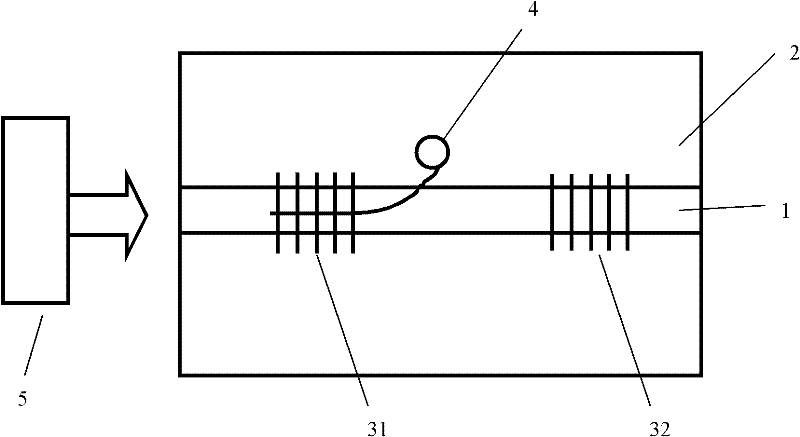
[0020] Embodiment 1, a single-mode fiber laser with a micro-resonator structure, see figure 1 , the laser includes: an optical fiber, a first grating 31 , a second grating 32 and a pumping source 5 . A micro-resonant cavity 4 is arranged in the optical fiber. The shape of the micro-resonant cavity 4 is a ring and two tangent lines tangent to the ring, located at the junction of the cladding and the fiber core, and living between the first grating 31 and the second Between the gratings 32, the tangent on the left side passes through the first grating 31; the pumping source 5 pumps the end face of the optical fiber.
[0021] Wherein the micro-resonant cavity 4 is formed by exposing the optical fiber with a femtosecond laser, and the refractive index of the exposed place is higher than that of the surrounding medium.
[0022] The parameters of each part are: the radius of the core 1 is 2 microns; the thickness of the cladding 2 is 58.5 microns; the fiber grating 31 is totally re...
Embodiment approach 2
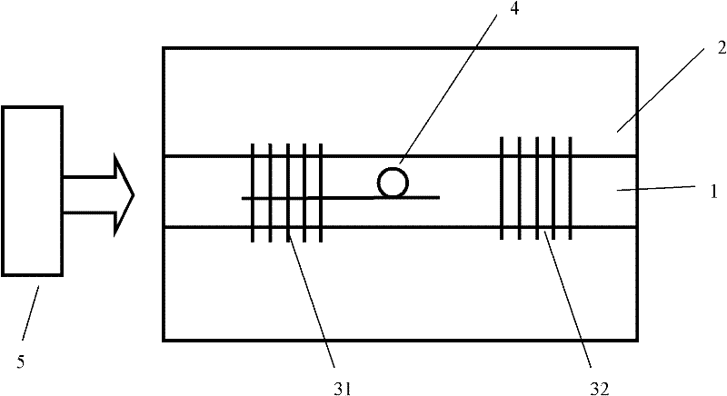
[0023] Embodiment 2, a single-mode fiber laser with a micro-resonator structure, see figure 2 , the laser includes: an optical fiber, a first grating 31 , a second grating 32 and a pumping source 5 .
[0024] A micro-resonant cavity 4 is arranged in the optical fiber. The shape of the micro-resonant cavity 4 is a ring and a tangent to the ring, located at the junction of the cladding and the core, and between the first grating 31 and the second grating. 32, the tangent passes through the first grating 31; the pumping source 5 pumps the end face of the optical fiber.
[0025] Wherein the micro-resonant cavity 4 is formed by exposing the optical fiber with an ultraviolet laser, and the refractive index of the exposed place is higher than that of the surrounding medium.
[0026] The parameters of each part are: the radius of the core 1 is 5 microns; the thickness of the cladding 2 is 57.5 microns; the fiber grating 31 is totally reflective to the light waves with a wavelength o...
Embodiment approach 3
[0027] Embodiment 3, a single-mode fiber laser with a micro-resonator structure, see image 3 , the laser includes: an optical fiber, a first grating 31 , a second grating 32 and a pumping source 5 .
[0028] A micro-resonant cavity 4 is arranged in the optical fiber, the shape of the micro-resonant cavity 4 is a ring and two tangents tangent to the ring, located in the fiber core, and between the first grating 31 and the second grating 32, The tangent on the left side passes through the first grating 31; the pumping source 5 pumps the end face of the optical fiber.
[0029] Wherein the micro-resonant cavity 4 is formed by exposing the optical fiber with a femtosecond laser, and the refractive index of the exposed place is higher than that of the surrounding medium.
[0030] The parameters of each part are: the radius of the core 1 is 8 microns; the thickness of the cladding 2 is 54.5 microns; the fiber grating 31 is totally reflective to the light waves with a wavelength of ...
PUM
 Abstract
Description
Claims
Application Information
 - R&D
- Intellectual Property
- Life Sciences
- Materials
- Tech Scout
- Unparalleled Data Quality
- Higher Quality Content
- 60% Fewer Hallucinations
Browse by: Latest US Patents, China's latest patents, Technical Efficacy Thesaurus, Application Domain, Technology Topic, Popular Technical Reports.
© 2025 PatSnap. All rights reserved.Legal|Privacy policy|Modern Slavery Act Transparency Statement|Sitemap|About US| Contact US: help@patsnap.com