Temperature controller assembly structure and temperature controller using same

A technology for assembling structure and thermostat, applied in the direction of thermal switch parts, etc., can solve the problems that the conductive column 05 cannot be pre-installed, it is difficult to ensure the qualified rate of assembly quality, and the automation of product assembly cannot be realized, so as to achieve stable structure and production. High efficiency and large overcurrent effect

Inactive Publication Date: 2011-05-25
吉庆龙
View PDF8 Cites 4 Cited by
  • Summary
  • Abstract
  • Description
  • Claims
  • Application Information

AI Technical Summary

Problems solved by technology

But the thermostat of this structure has the following defects: 1. Because the riveting mounting holes provided on the moving contact piece 03 and the static contact piece 04 are all larger than the diameter of the conductive column 05, that is, before the riveting, the moving contact piece 03 And the static contact piece 04 is loosely fitted with the conductive column 05, so that the conductive column 05 cannot be pre-installed on the movable contact piece 03 or the static contact piece 04 (such as Figure 2 to Figure 5 As shown), all the assembly and riveting processes need to be completed manually by the same employee, which cannot realize the automation of product assembly, the production efficiency is low, and it is difficult to ensure the qualified rate of assembly quality during manual operation
2. The moving contact piece 03 and the static contact piece 04 are loosely matched with the conductive column 05, so after assembly, the moving contact piece 03 and the static contact piece 04 are only closely connected to the riveted end of the conductive column 04 to realize electrical connection, the contact area is limited, and the resistance Larger, less overcurrent, not suitable for large current control occasions, and has certain safety hazards

Method used


Image

  • Temperature controller assembly structure and temperature controller using same
  • Temperature controller assembly structure and temperature controller using same
  • Temperature controller assembly structure and temperature controller using same

Examples


Embodiment Construction

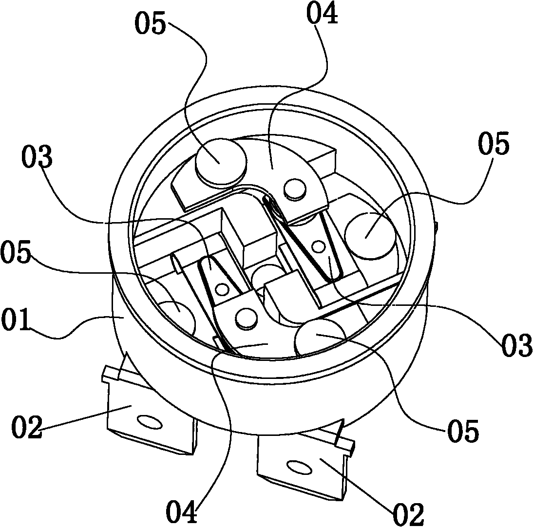
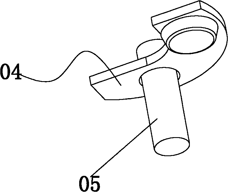
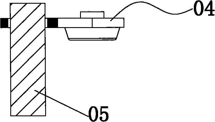
[0037] like Figure 6 to Figure 15 As shown, a thermostat assembly structure includes a base 1, two pairs of power terminals arranged at the bottom of the base 1, and two movable contact pieces and two static contact pieces arranged in the base 1. The said The power terminal includes a first power input terminal 21 , a first power output terminal 22 , a second power input terminal 23 and a second power output terminal 24 , and the moving contact piece includes a first moving contact piece 31 and a second moving contact piece 32 , the static contact piece includes a first static contact piece 41 and a second static contact piece 42, wherein, the first movable contact piece 31 is connected with the first power input terminal 21 by riveting to achieve electrical connection after interference fit with the screw 5, The first static contact piece 41 is riveted to the first power output terminal 22 after interference fit with the screw 5 to realize electrical connection, and the seco...


PUM


Abstract

The invention discloses a temperature controller assembly structure. The temperature controller assembly structure comprises a base, at least one pair of power terminals, at least one movable contact piece and at least one fixed contact piece, wherein the at least one pair of power terminals is arranged outside the base; the movable contact piece and the fixed contact piece are arranged in the base; the movable contact piece is electrically connected with one of the power terminals; the fixed contact piece is electrically connected with the other power terminal; and the movable contact piece is elastically pressed against the fixed contact piece to realize electrical connection. The temperature controller assembly structure is characterized in that: the movable contact piece and the fixed contact piece are in tight fit with a screw respectively and then are connected with each power terminal by spin riveting. A temperature controller is characterized by comprising the temperature controller assembly structure, wherein a movable contact piece control member which can separate the movable contact piece from the fixed contact piece is arranged in the base. An assembly process can be automated, the labor resource is saved, the production efficiency is high, and the assembly quality can be guaranteed; in addition, the movable contact piece and the fixed contact piece are in tight fit with the screw, so the structure is more stable, has large contact area, low resistance and high over-current, is suitable for high-current situations and has high safety.

Description

Technical field: [0001] The invention relates to a thermostat assembly structure and a thermostat used therefor. Background technique: [0002] like figure 1 As shown, an existing thermostat mainly includes a base 01, a power terminal 02 arranged at the bottom of the base, a moving contact piece 03, a static contact piece 04 and a moving contact piece control member arranged in the base 01 (not shown in the figure), wherein, the moving contact piece 03 and the static contact piece 04 are respectively riveted to different power terminals 02 through a conductive column 05 to achieve electrical connection, and the moving contact piece 03 and the static contact piece 04 are elastically offset to achieve electrical connection . When in use, stick the thermostat on the temperature collection point. When the temperature of the collection point exceeds the use range, the moving contact piece control part drives the moving contact piece 03 away from the static contact piece 04, cut...

Claims


Application Information

Patent Timeline
Patent Type & Authority Applications(China)
IPC IPC(8): H01H37/64H01H37/46
Inventor 吉庆龙
Owner 吉庆龙
Why Eureka
Try Eureka