Method and device for determining label flowing direction

A technology of flow direction and determination method, applied in the field of communication, can solve problems such as waste of resources, achieve the effect of saving resources and filling technical gaps

Inactive Publication Date: 2011-05-25
TIANJIN ZHONGXING SOFTWARE
View PDF0 Cites 3 Cited by
  • Summary
  • Abstract
  • Description
  • Claims
  • Application Information

AI Technical Summary

Problems solved by technology

[0004] In view of the waste of resources caused by the need to judge the flow direction of the label through special sensing equipment or human operation, the present invention aims to provide an improved solution for determining the flow direction of the label to solve at least one of the above problems

Method used


Image

  • Method and device for determining label flowing direction
  • Method and device for determining label flowing direction
  • Method and device for determining label flowing direction

Examples


Embodiment 1

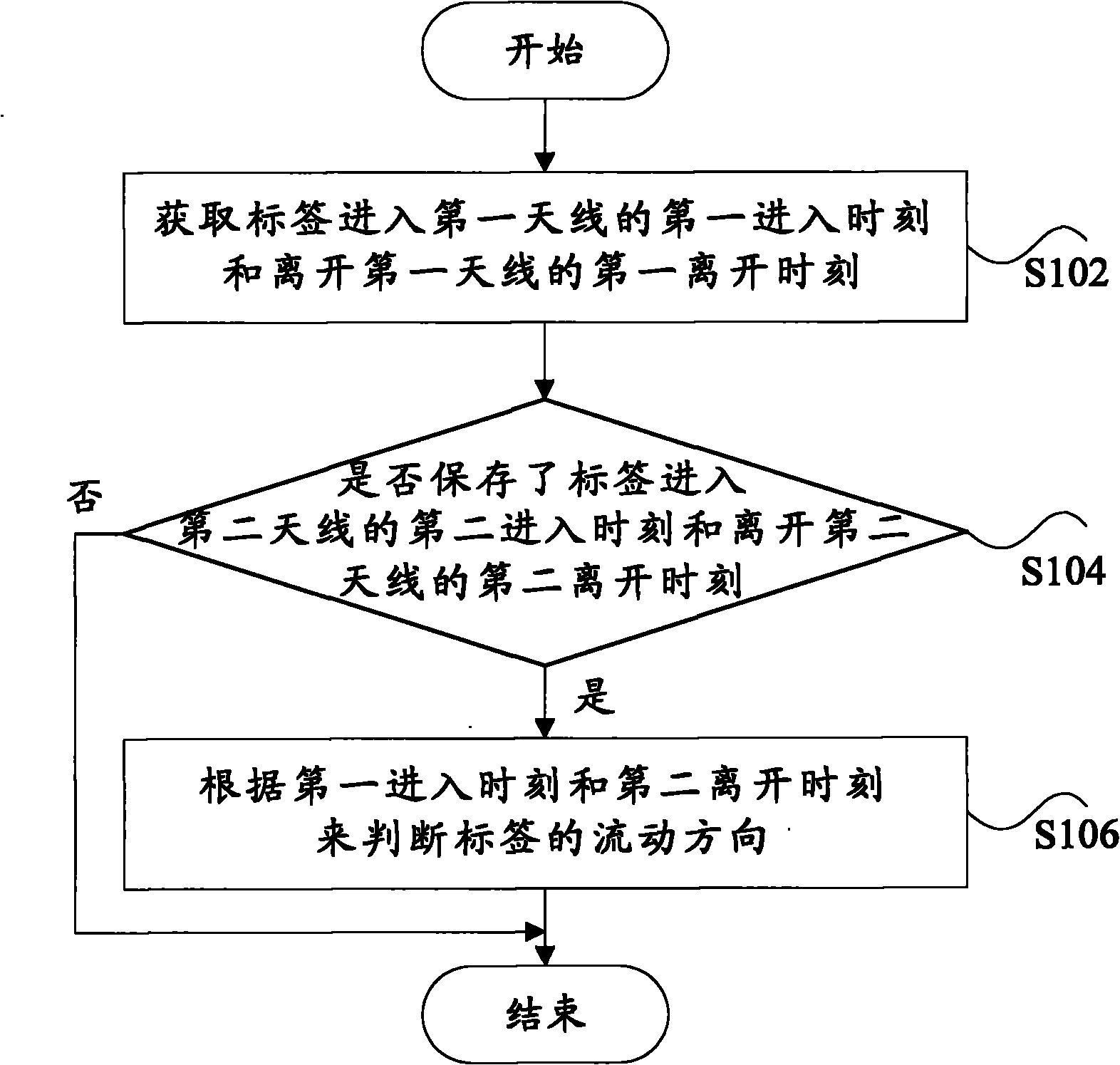
[0031] According to an embodiment of the present invention, a method for determining the flow direction of tags is provided, which is applied to an RFID system, and the RFID system includes one or more readers, tags, a first antenna, and a second antenna corresponding to the first antenna, Wherein, the first antenna and the second antenna are respectively connected to the reader. figure 1 It is a flowchart of a method for determining the direction of label flow according to an embodiment of the present invention. The following uses an example of label flow from the second antenna to the first antenna. For example, the label leaves the coverage area of ​​the second antenna and enters the first antenna. After the coverage area of ​​the antenna, proceed as figure 1 The following operations are shown (step 102 to step 106).

[0032] Step 102, acquire the first entry time when the tag enters the first antenna and the first departure time when the tag leaves the first antenna. Tha...

Embodiment 2

[0042] In this embodiment, a preferred implementation manner is provided.

[0043] For the above-mentioned process of determining the flow direction of the first antenna, if the first departure time cannot be successfully obtained within a certain period of time, it means that the tag has been stranded in the first antenna. At this time, the determination of the tag can be given up. Flow direction.

[0044] Similarly, for the above-mentioned second antenna, if the second departure time cannot be successfully acquired within a certain period of time when judging the flow direction, it means that the tag is stuck in the second antenna.

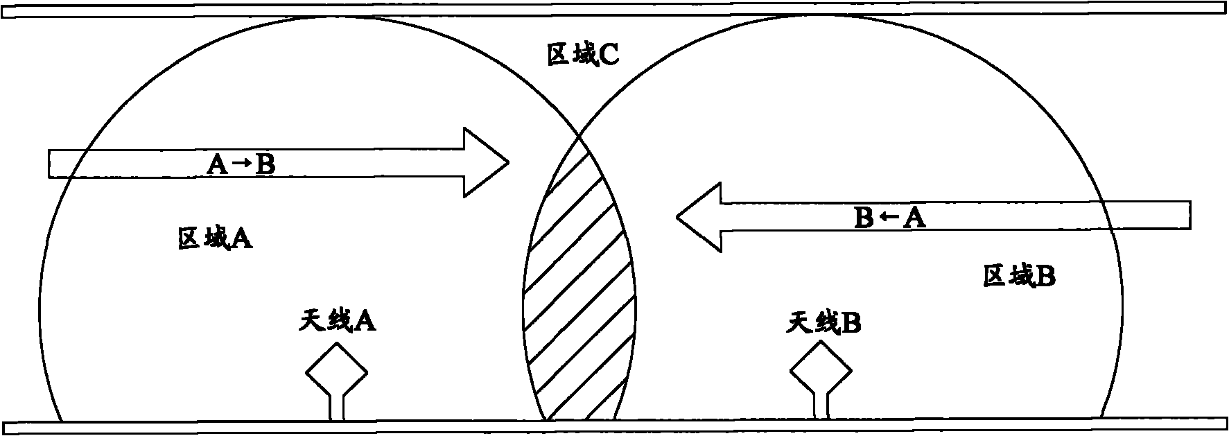
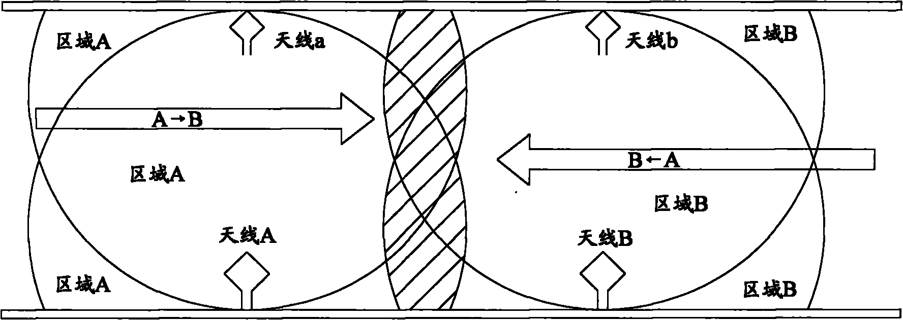
[0045] figure 2 is a schematic diagram of the application scenario of the embodiment of the present invention, such as figure 2 As shown, in the RFID system, two adjacent antennas (that is, the above-mentioned first antenna and second antenna, represented by antenna A and antenna B) are placed on a straight line, and these two antennas are a...


PUM


Abstract

The invention provides a method and a device for determining a label flowing direction, which are applied to a radio frequency identification system comprising one or more readers, a label, a first antenna and a second antenna. The first antenna and the second antenna are connected to the one or more readers respectively, and the method for determining the label flowing direction comprises the following steps of: acquiring a first entering moment when the label enters a coverage area of the first antenna and a first departure moment when the label departures from the coverage area of the first antenna; judging whether a second entering moment when the label enters the coverage area of the second antenna and a second departure moment when the label departures from the coverage area of the second antenna are stored; and if the second entering moment and the second departure moment are stored, determining the flowing direction of the label according to the first entering moment and the second departure moment. Through the method and the device, the problem that the flowing direction of the label is needed to be judged through special sensing equipment or manual operation in the prior art is solved, resources are saved, and the technology gap in the field of radio frequency identification devices (RFID) is filled.

Description

technical field [0001] The present invention relates to the field of communications, in particular to a method and device for determining the flow direction of labels. Background technique [0002] Radio Frequency Identification (RFID) technology is a non-contact automatic identification technology. An RFID-based system mainly includes a reader and an electronic tag (hereinafter referred to as a tag), wherein the identification of the tag by the reader is completed through the interaction between the reader and the tag. The specific identification operation is: the reader sends a command to the tag through a radio frequency signal, and accordingly, the tag responds to the command of the reader through a radio frequency signal, so as to realize the identification of the tag by the reader. [0003] At present, in RFID-based systems, judging the flow direction of tags has very important application significance. For example, for a company, it is very important for the effecti...

Claims


Application Information

Patent Timeline
IPC IPC(8): G06K7/00
Inventor 赵景喜
Owner TIANJIN ZHONGXING SOFTWARE
Why Eureka
Try Eureka