
Wind sensor system using blade signals

A sensor signal, blade technology, applied in the field of wind speed field measurement system, can solve problems such as being too expensive

Active Publication Date: 2011-05-25
SSB WIND SYST
View PDF6 Cites 10 Cited by
  • Summary
  • Abstract
  • Description
  • Claims
  • Application Information

AI Technical Summary

Problems solved by technology

More importantly, SODAR and LIDAR systems are too expensive for use in commercial wind turbines (i.e. beyond the prototype stage)

Method used


Image

  • Wind sensor system using blade signals
  • Wind sensor system using blade signals
  • Wind sensor system using blade signals

Examples


Embodiment approach

[0056] refer to image 3 , with S 0 Denotes sensor signals from sensors 108 positioned on the rotor hub or blades, where sensor signal S corresponds to at least one wind velocity field characteristic denoted by C. The sensor signal S passes through a calibration arrangement 110 which provides variable gain and offset to the sensor signal so as to always substantially calibrate the sensor signal, thus producing a balanced sensor signal S 1 . If there is noise in the sensor signal, a low-pass filter can be incorporated in the correction device to attenuate or remove this noise.

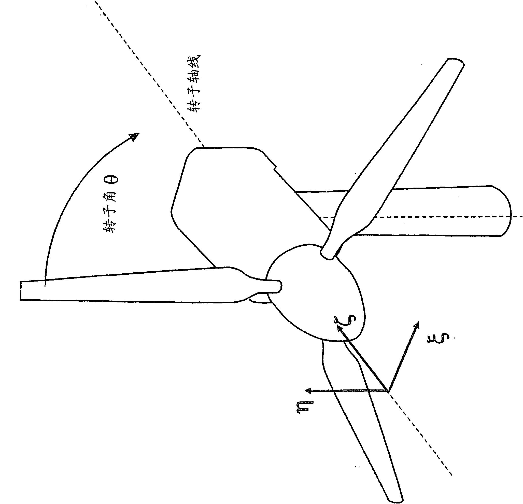
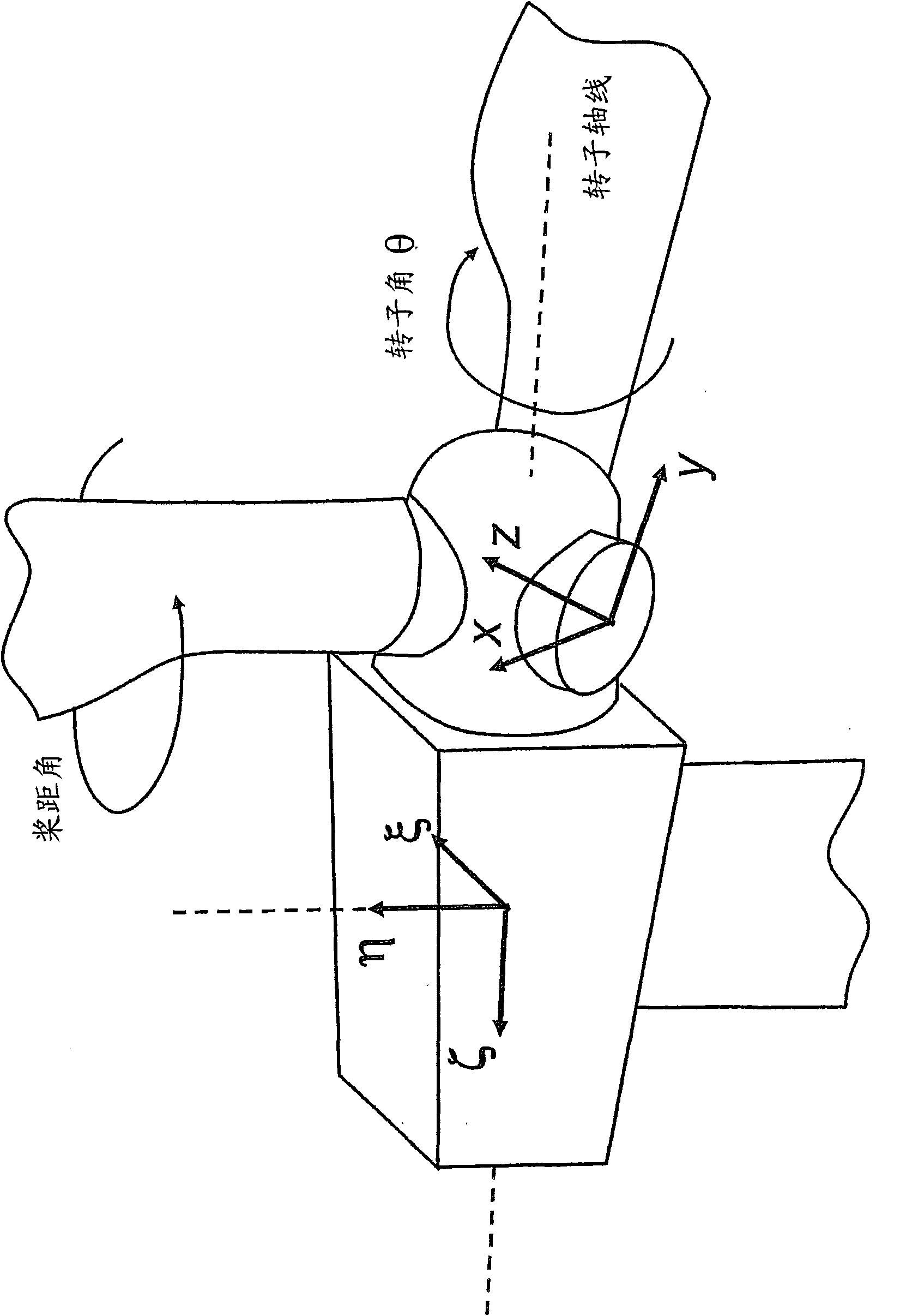
[0057] In the case of misalignment between the rotor axis and the wind direction, or in the presence of wind shear, the rotation of the rotor (turned angle θ) within the sensor signal S 1 produces a cyclic change added to a constant value. Let A represent the amplitude of the cyclic change, and use Denotes the angle θ at which the maximum value occurs, and denote the sensor signal S by K 1 consta...


PUM


Abstract

The present invention relates to a wind-velocity-field measurement system for use in a wind turbine having a rotor with' two or more blades, comprising at least one sensor-signal obtained by measuring a physical quantity on at least one of the blades, the physical quantity being indicative of at least one wind-velocity-field characteristic; a table (140, 142, 144) build for a plurality of wind conditions by associating values characterizing the at least one sensor-signal with values of the at least one wind-velocity-field characteristic, and; searching means (150, 152, 154) for determining from the table a value of the at least one wind-velocity-field characteristic for a current wind condition given values characterizing the at least one sensor-signal. Methods for measuring wind-velocity-field ina wind turbine having a rotor with' two or more blades and related wind turbines and turbine control systems are also disclosed in the invention.

Description

technical field [0001] The present invention relates to a wind speed field measurement system for use in a wind turbine, and more particularly to a wind speed field measurement system for use in a wind turbine with a rotor with two or more blades. The invention also relates to a method of measuring a wind speed field in a wind turbine having a rotor with two or more blades and to a related wind turbine and turbine control system. Background technique [0002] Most modern wind turbines exclusively use blades that are pitchable about their longitudinal axis to adjust the angle of attack of the blades and thus the lift and drag of the blades. The common pitch motion between all the blades connected to the rotor is used to regulate the aerodynamic forces derived from the wind, while the individual pitch control is mainly used to mitigate or reduce the impact on the blades during normal operation in unsteady wind conditions. load. [0003] In order for individual pitch control ...

Claims


Application Information

Patent Timeline
Patent Type & Authority Applications(China)
IPC IPC(8): G01P5/02G01P5/04F03D1/00F03D7/02
CPCF05B2270/32F05B2270/708F05B2270/802Y02E10/722Y02E10/723F03D7/042F05B2240/221F05B2260/821Y02E10/72F05B2270/808F03D11/0091F03D17/00F05B2270/321F03D17/007
Inventor 法比奥·伯托洛蒂詹斯·范谢尔夫
Owner SSB WIND SYST
Learn More