
Conductor arrangement for a resistive switching element having at least two composite conductors made from superconducting conductor bands

A switching element, resistive technology, applied in the field of conductor configuration, to achieve the effect of compact structure

Inactive Publication Date: 2011-05-18
SIEMENS AG
View PDF1 Cites 14 Cited by
  • Summary
  • Abstract
  • Description
  • Claims
  • Application Information

AI Technical Summary

Problems solved by technology

However, here a problem arises in terms of the compressive strength of the coil

Method used


Image

  • Conductor arrangement for a resistive switching element having at least two composite conductors made from superconducting conductor bands
  • Conductor arrangement for a resistive switching element having at least two composite conductors made from superconducting conductor bands
  • Conductor arrangement for a resistive switching element having at least two composite conductors made from superconducting conductor bands

Examples


Embodiment Construction

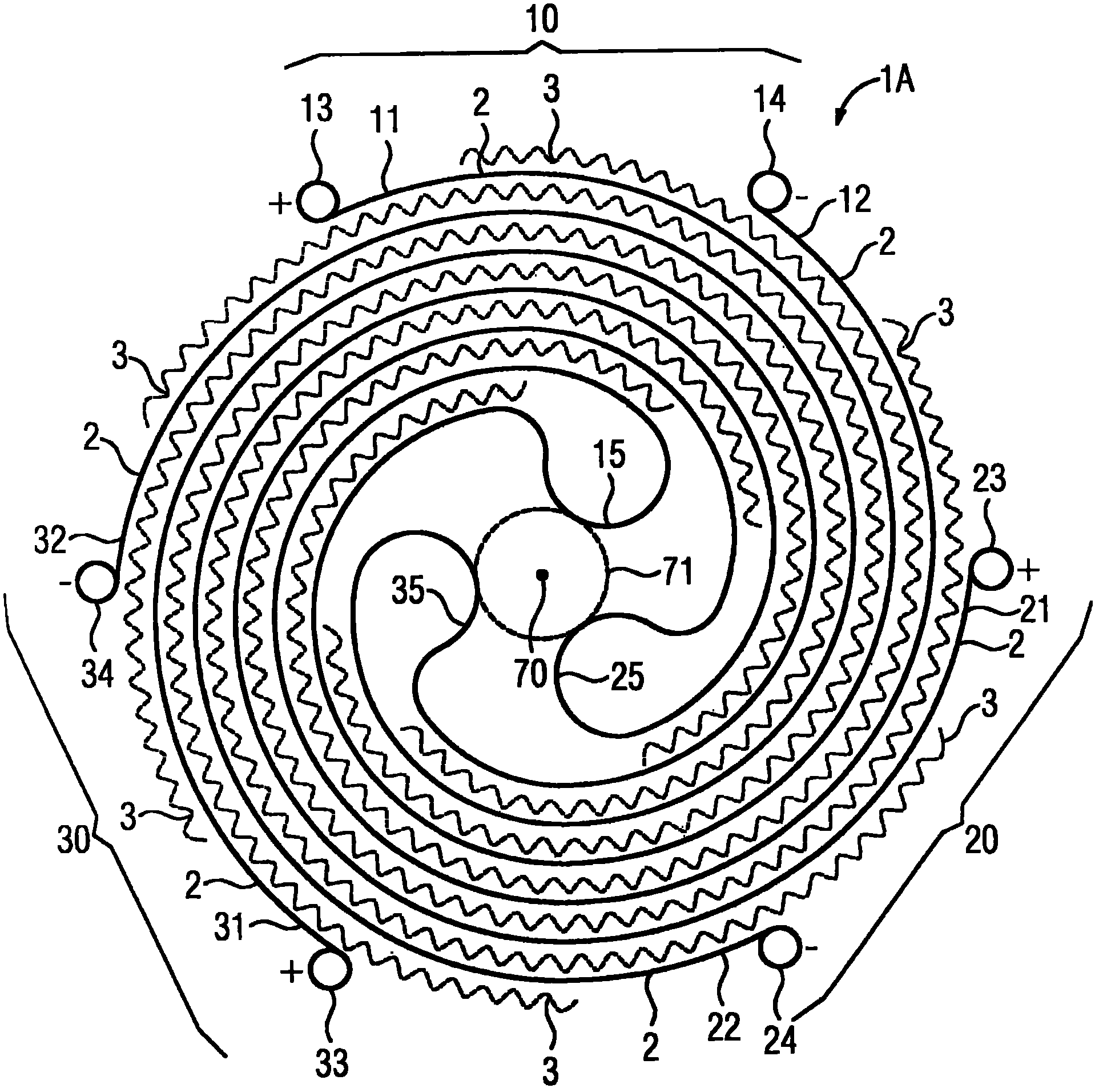
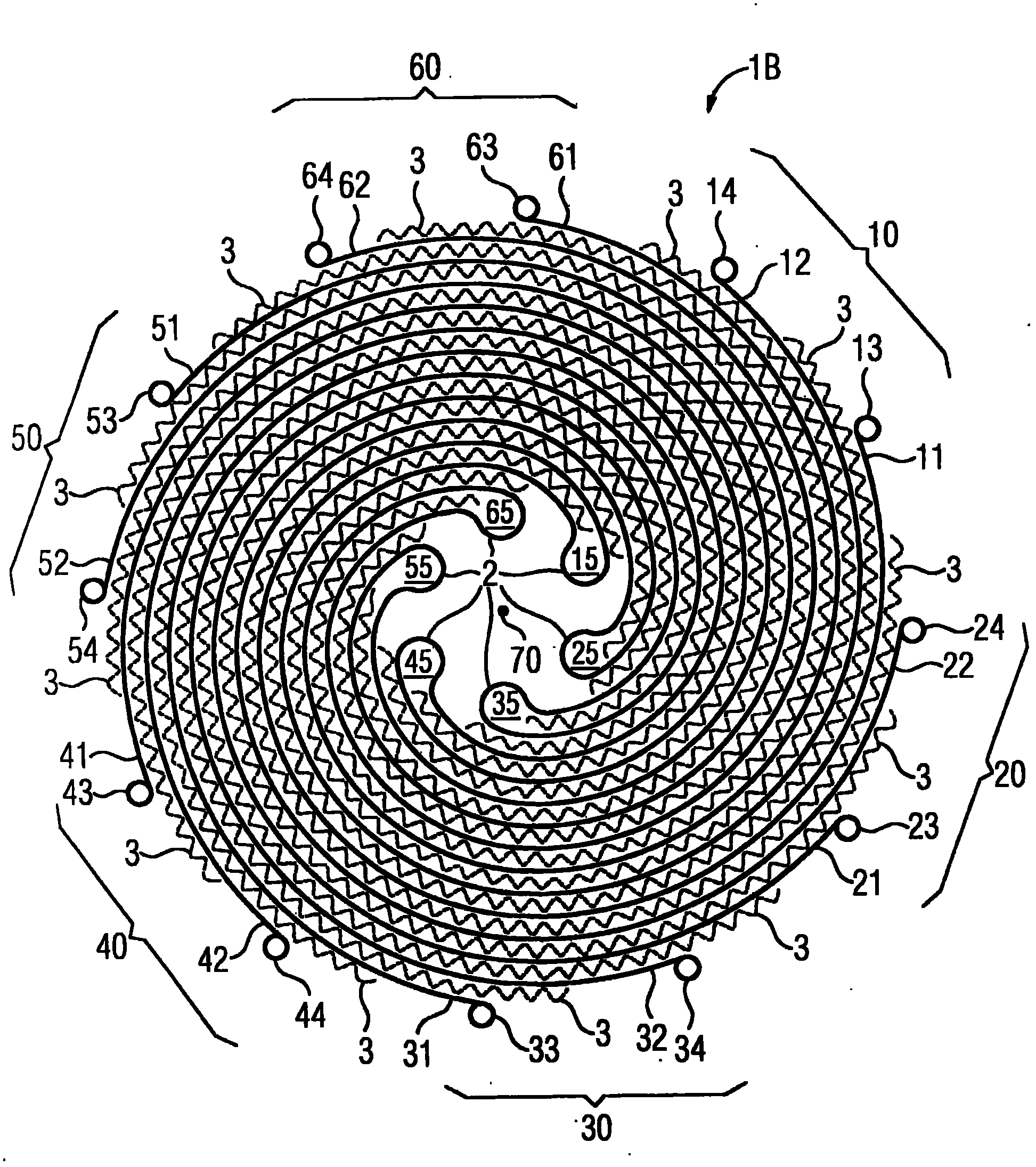
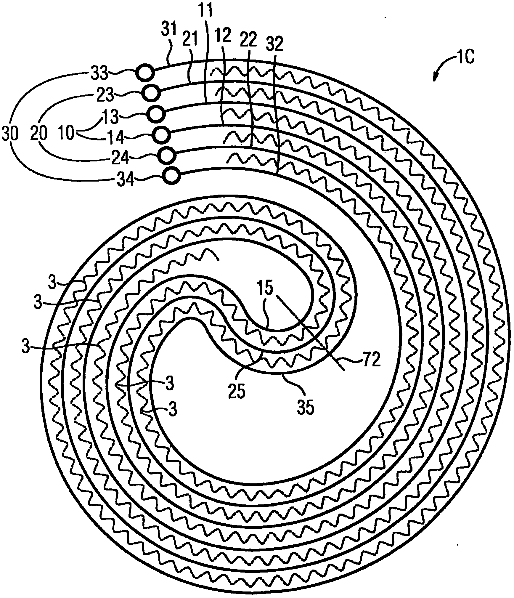
[0034] figure 1 A conductor arrangement 1A according to the invention for a resistive switching element is schematically shown, which comprises three conductor combinations, namely conductor combinations 10 , 20 and 30 . Each conductor combination 10 , 20 , 30 consists of at least one superconducting conductor strip 2 . Each conductor combination 10 , 20 , 30 has two conductor parts 11 , 12 or 21 , 22 or 31 , 32 running in parallel to form a double-wire structure, which each have a central connection point 15 , 25 , 35 . The conductor assemblies 10 , 20 , 30 are arranged adjacent to one another in a common plane and are insulated from one another. The conductor assemblies 10 , 20 , 30 form a common coil winding, the turns of which extend essentially in the manner of a helix. The connection points 15 , 25 , 35 of the conductor assemblies 10 , 20 , 30 are each designed as part circles and are arranged in the plane tangential to a circle radius 71 around the center 70 of the he...


PUM


Abstract

The invention relates to a conductor arrangement (1A) for a resistive switching element, comprising at least a first and at least a second conductor connection (10, 20, 30) disposed in a mutual plane adjacent to each other and insulated against each other. The composite conductors (10, 20, 30) each have two conductor parts (11, 12, 21, 22, 31, 32) extending parallel, and forming a bifilar construction, said conductor parts being constructed from at least one supraconducting conductor band (2). The composite conductors (10, 20, 30) are formed into a coil winding, wherein the windings thereof substantially extend in the manner of a spiral, and are insulated against each other by means of a spacer (3).

Description

technical field [0001] The invention relates to a conductor arrangement for a resistive switching element comprising at least one first and at least one second conductor combination. These conductor assemblies each comprise two parallel-running conductor parts forming a double-wire structure, each consisting of at least one superconducting conductor strip. Such a conductor arrangement is known, for example, from US6275365B1. Background technique [0002] In the grid, electricity is delivered by generators to users. Short circuits should be avoided during this process as short circuits may cause irreparable damage to the device. One possibility for avoiding short circuits in the grid is to use so-called short-circuit current limiters. [0003] A superconductor short-circuit current limiter is a particularly suitable form in terms of switching characteristics and operating costs. They operate with no or only small power losses based on superconductivity and are characteriz...

Claims


Application Information

Patent Timeline
Patent Type & Authority Applications(China)
IPC IPC(8): H01F6/06
CPCH01F6/06H01L39/16H01F27/2871H01F27/323H10N60/30H01F6/008H02H7/222H10N60/84
Inventor 汉斯-彼得·克莱默
Owner SIEMENS AG
Learn More