
Hierarchical heat driving floor planning and layout method

A layout planning and layout method technology, which is applied in special data processing applications, instruments, electrical digital data processing, etc., can solve the problem of not considering the influence of heat source on the device layer, so as to avoid repeated thermal calculation process, optimize area and interconnection Line length, the effect of eliminating hot spots

Inactive Publication Date: 2011-05-18
WUHAN UNIV OF TECH
View PDF1 Cites 7 Cited by
  • Summary
  • Abstract
  • Description
  • Claims
  • Application Information

AI Technical Summary

Problems solved by technology

[0007] However, since the power density diagram only considers the ideal power distribution of a certain device layer, and does not consider the influence of heat sources between device layers, high power density devices will appear in the vertical area of ​​a stack during floorplanning / layout

Method used


Image

  • Hierarchical heat driving floor planning and layout method
  • Hierarchical heat driving floor planning and layout method
  • Hierarchical heat driving floor planning and layout method

Examples


Embodiment Construction

[0028] Embodiments of the present invention will now be described with reference to the drawings, in which like reference numerals represent like elements.

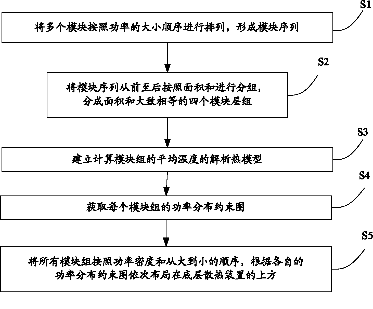
[0029] refer to figure 1 , the layered heat-driven layout planning and layout method of the present invention includes the following steps:

[0030] Step S1, arranging multiple modules according to the order of power to form a module sequence;

[0031] Step S2, group the module sequence from front to back according to the area sum, and divide it into four module layer groups whose area sum is approximately equal, so that the modules with the largest power density and the largest power density will be gathered in the same group;

[0032] Step S3, establishing an analytical thermal model for calculating the average temperature of the module group;

[0033] Step S4, obtaining the power distribution constraint graph of each module group;

[0034] Step S5, according to the power density and order from large to small, all th...


PUM


Abstract

The invention discloses a hierarchical heat driving floor planning and layout method which comprises the following steps of: firstly, arranging a plurality of modules according to a power sequence, and forming a module sequence; secondly, grouping the module sequence from front to back according to an area sum, dividing into a plurality of module layer groups with approximately equal area sum; thirdly, establishing an analysis heat mold for calculating the average temperature of the module groups; fourthly, acquiring a power distribution constraint graph of each module group; and fifthly, sequentially arranging the module groups above a heat dissipating device at the bottom layer according to the power density, the sequence from big to small and the respective power distribution constraint graph. In the method, a three-dimensional layout problem is converted to a two-dimensional layout problem, thereby avoiding putting a high-power density device in a pile of vertical regions, realizing power density balanced distribution in vertical and horizontal directions, efficiently reducing the hot spot amount and optimizing the chip area and the interconnecting wire length.

Description

technical field [0001] The invention relates to a layered heat-driven three-dimensional chip, in particular to a layered heat-driven layout planning and layout method of the three-dimensional chip. Background technique [0002] The three-dimensional integration technology that stacks multiple device levels together can significantly increase the stacking density of transistors and reduce the chip area, while reducing the wiring distance, so it can reduce the interconnect delay problem caused by the exponentially increasing circuit complexity ( See literature [1]). However, due to the rapid increase in power density caused by multiple devices stacked in layers, and the thermal conductivity of insulators inserted between device layers is lower than that of silicon or metal materials, heat dissipation has become the most serious challenge for 3D IC design . Generally speaking, in order to finally achieve better heat dissipation effect, the heat dissipation problem should be c...

Claims


Application Information

Patent Timeline
Patent Type & Authority Applications(China)
IPC IPC(8): G06F17/50
Inventor 徐宁程平阶郑飞
Owner WUHAN UNIV OF TECH
Learn More