
Spatial six-degree-of-freedom motion platform modal control method

A modal control, motion table technology, applied in non-electric variable control, vehicle position/route/height control, position/direction control, etc., can solve the problem of not being able to essentially improve and improve the control performance of a six-degree-of-freedom hydraulic motion table , the ambiguity of the corresponding relationship, the neglect of strong dynamic coupling characteristics, etc., to achieve the effect of improving the reproduction of single-degree-of-freedom motion and multi-degree-of-freedom compound motion, weakening the coupling effect, and increasing the bandwidth of the degree of freedom

Inactive Publication Date: 2011-05-18
HARBIN INST OF TECH
View PDF6 Cites 30 Cited by
  • Summary
  • Abstract
  • Description
  • Claims
  • Application Information

AI Technical Summary

Problems solved by technology

The six-degree-of-freedom hydraulic motion table in space is a closed multi-chain structure composed of a hydraulic cylinder composed of six piston rods and a hydraulic cylinder, a motion platform and a fixed base platform. This type of motion table belongs to a class of highly nonlinear and strong power The mechanical-electrical-hydraulic hybrid system coupled with science and engineering adopts the traditional hinge point space single-channel control method. The existing domestic and foreign space six-degree-of-freedom hydraulic motion table control theory is also based on the degree of freedom or hinge point space for controller design. , in order to improve the system control performance, but these control technologies ignore the strong dynamic coupling characteristics of the six-degree-of-freedom hydraulic motion table itself, and the corresponding relationship between the degree of freedom space or hinge point space and the hydraulic motion table mode is not clear However, the existing control technology cannot essentially improve and enhance the control performance of the six-degree-of-freedom hydraulic motion table.

Method used


Image

  • Spatial six-degree-of-freedom motion platform modal control method
  • Spatial six-degree-of-freedom motion platform modal control method
  • Spatial six-degree-of-freedom motion platform modal control method

Examples


Embodiment 1

[0015] Example 1: Combining figure 1 , a modal control method for a space six-degree-of-freedom motion platform of the present invention, the steps are as follows:

[0016] Step 1: Use the modal matrix of the six-degree-of-space hydraulic motion table to transform the physical space system into the modal space, and construct a six-degree-of-freedom uncoupled hydraulic motion table in the modal space, that is, the spool of the hydraulic motion table in the physical space The input signal is converted into a modal spool input signal, and the hydraulic cylinder displacement output by the motion table or the output pose physical quantity after positive solution is transformed into a modal displacement or modal pose output signal. After the transformation from the physical space to the modal space, the space The six-degree-of-freedom hydraulic motion table is transformed into a mechanically coupled motion system, which is the key to the realization of the modal decoupling control t...

Embodiment 2

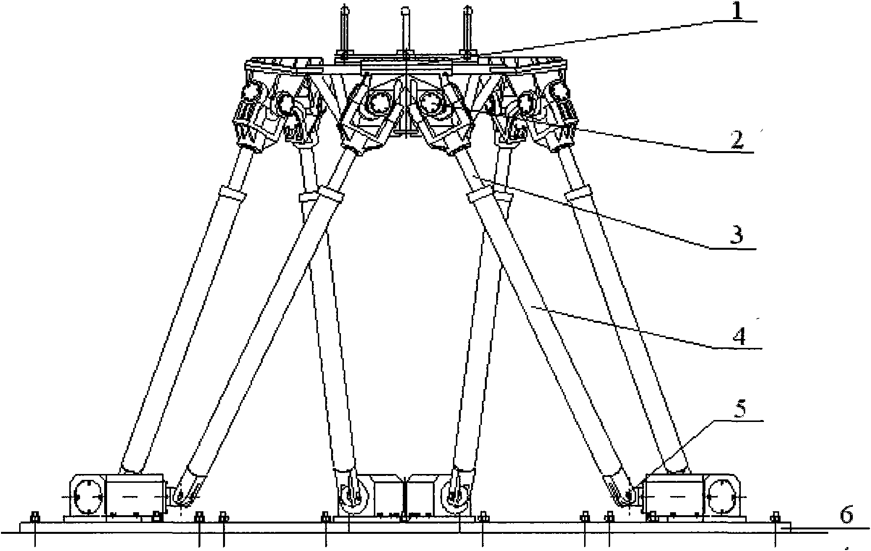
[0022] Example 2: Combining figure 1 , figure 1 It is a composition diagram of a six-degree-of-freedom motion platform. In the figure: (1) motion platform, (2) upper connecting hinge, (3) piston rod, (4) hydraulic cylinder, (5) lower connecting hinge, (6) base platform .

[0023] The total stroke of the hydraulic cylinder is 0.74m, and the length of the hydraulic cylinder in the middle position is 1.83m. The generalized pose expected by the motion platform is a 6-dimensional vector sx des , the expected displacement of the hydraulic cylinder relative to the median is a 6-dimensional vector l des , the spool driving voltage signal input by the motion table is a 6-dimensional vector V e , the actual output hydraulic cylinder displacement signal of the motion table is a 6-dimensional vector l.

[0024] There is a strong coupling between the hydraulic cylinders and degrees of freedom of the six-degree-of-freedom hydraulic motion table in space, and there is a coupling effect ...

Embodiment 3

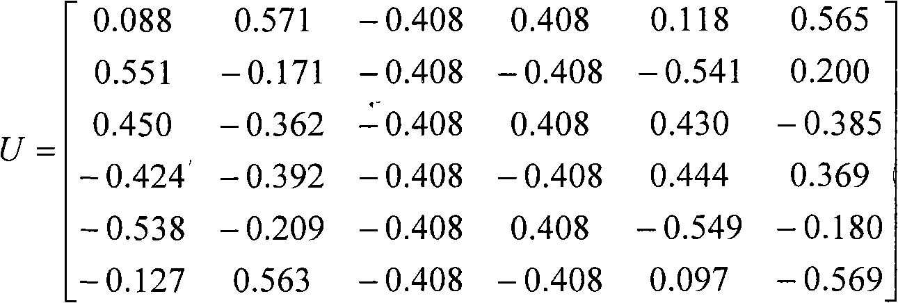
[0025] Example 3: Binding figure 2 , the reference input signals in the signal generator in this example include constant value pose input signal, sinusoidal pose input signal and random pose input signal. The kinematics inverse solution module analyzes and calculates the 6-dimensional hydraulic cylinder displacement signal of the motion table corresponding to the given reference pose input signal according to the geometric principle des . The modal controller will expect the physical input displacement signal l des Transform the actual output physical displacement signal l of the six-degree-of-freedom hydraulic motion table into a modal signal Control, and then inversely transform the output modal spool displacement signal to the physical space to drive the servo valve to realize the drive and control of the motion table. The modal matrix used in the controller is:

[0026] U = 0.088 ...


PUM


Abstract

The invention provides a spatial six-degree-of-freedom motion platform modal control method. In the invention, a spatial six-degree-of-freedom motion platform modal matrix is used to convert a strong-coupling physical space system into a decoupled modal space system, a modal control concept is introduced on the basis of the conventional spatial six-degree-of-freedom hydraulic motion platform control, the modal conversion matrix is used to decouple a strong dynamic coupling six-degree-of-freedom hydraulic motion platform, an expected physical input signal and a motion platform actual output signal are converted into modal signals to perform independent modal control regulation, the drive and control of the spatial six-degree-of-freedom hydraulic motion platform are realized, the coupling influences among the actuators and degrees of freedom in a spatial six-degree-of-freedom hydraulic motion are weakened effectively, indexes such as the single degree of freedom motion and multiple degree of freedom motion reproduction of the six-degree-of-freedom hydraulic motion platform are improved, and the bandwidths of degrees of freedoms besides the close degree of freedom of a first order modal are improved.

Description

(1) Technical field [0001] The invention relates to electromechanical and hydraulic technologies, in particular to a modal control method for a space six-degree-of-freedom motion platform. (2) Background technology [0002] The six-degree-of-freedom hydraulic motion table in space is a kind of motion environment simulation test equipment. As an important test method, it provides a motion test environment for the development of large-scale equipment and instruments, which can effectively shorten the development cycle and save manpower and financial resources. It provides environmental support for the reliable and effective development of large-scale national defense equipment and precision instruments and the training of special personnel. The six-degree-of-freedom hydraulic motion table consists of a motion platform, an upper connecting hinge, a piston rod, a hydraulic cylinder, a lower connecting hinge, a base platform and related hydraulic piping systems. Under the drivin...

Claims


Application Information

Patent Timeline
IPC IPC(8): G05D1/00
Inventor 韩俊伟杨炽夫黄其涛张辉郑淑涛
Owner HARBIN INST OF TECH
Learn More