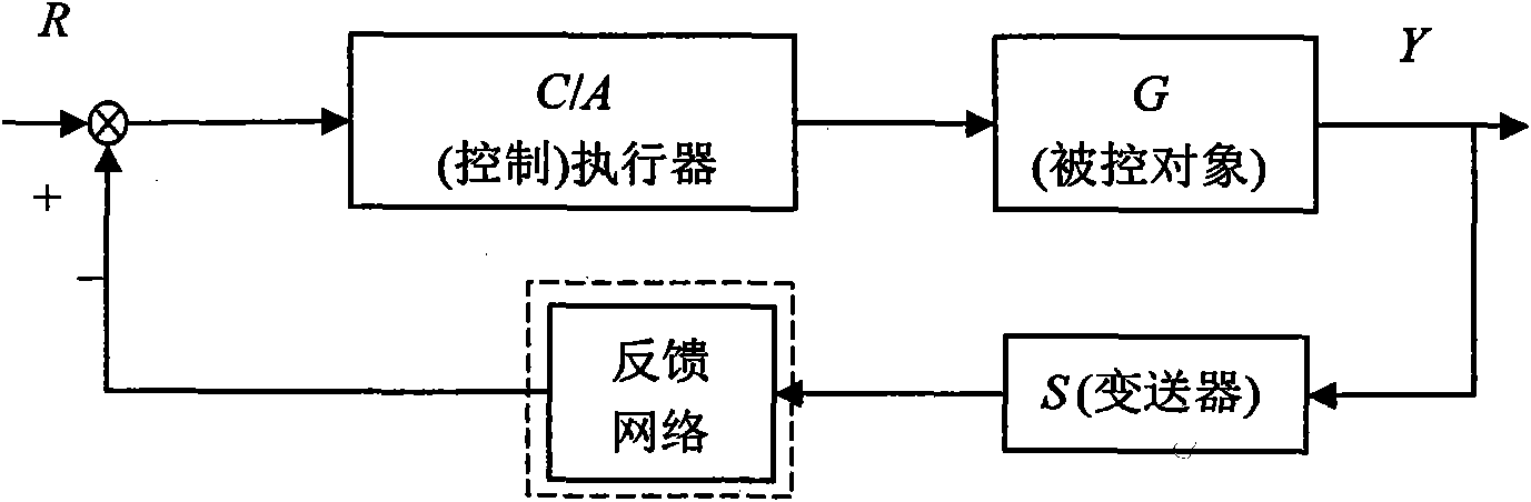
Delay compensation method with double adjustment function between transducer and (controller) executer
A technology of time delay compensation and compensation method, applied in the direction of comprehensive factory control, electrical program control, comprehensive factory control, etc., can solve problems such as deterioration of system control performance quality, system failure, and large economic investment.
- Summary
- Abstract
- Description
- Claims
- Application Information
AI Technical Summary
Problems solved by technology
Method used
Image

Examples
Embodiment Construction
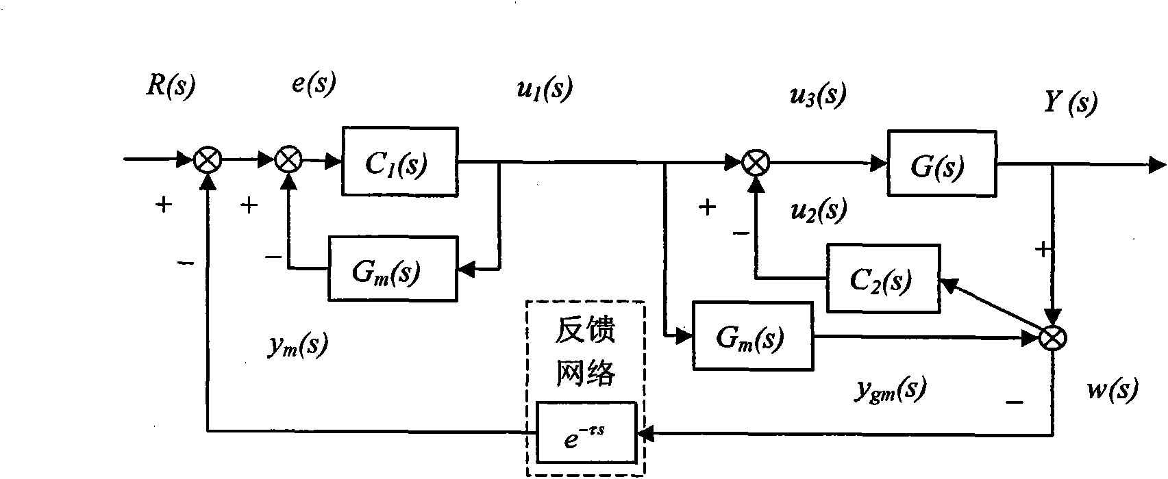
[0070] The following will refer to the attached image 3 Exemplary embodiments of the present invention are described in detail to make the above and other features and advantages of the present invention more apparent to those skilled in the art.
[0071] The specific implementation steps are as follows:
[0072] The first step: the output signal Y(s) of the transmitter node working in the time-driven mode to the controlled object G(s) and the estimated model G of the controlled object m (s) output signal y gm (s) for periodic sampling; for Y(s) and y gm (s) Implement subtraction to obtain the model deviation signal w(s); transmit w(s) to the (control) actuator node through the feedback network path;
[0073] Step 2: The (control) actuator node working in the event-driven mode is triggered by the feedback network path signal w(s), and the system given signal R(s) is connected to w(s) and y m (s) implement the subtraction operation to obtain the error signal e(s); implemen...
PUM
 Abstract
Description
Claims
Application Information
 - R&D
- Intellectual Property
- Life Sciences
- Materials
- Tech Scout
- Unparalleled Data Quality
- Higher Quality Content
- 60% Fewer Hallucinations
Browse by: Latest US Patents, China's latest patents, Technical Efficacy Thesaurus, Application Domain, Technology Topic, Popular Technical Reports.
© 2025 PatSnap. All rights reserved.Legal|Privacy policy|Modern Slavery Act Transparency Statement|Sitemap|About US| Contact US: help@patsnap.com