
High resolution optical encoder systems, devices and methods

An optical encoder, optical transmission technology, applied in the field of motion encoder, can solve problems such as increasing design and IC cost

Inactive Publication Date: 2011-05-18
AVAGO TECH WIRELESS IP SINGAPORE PTE
View PDF7 Cites 10 Cited by
  • Summary
  • Abstract
  • Description
  • Claims
  • Application Information

AI Technical Summary

Problems solved by technology

The use of so many comparators increases design and IC cost

Method used


Image

  • High resolution optical encoder systems, devices and methods
  • High resolution optical encoder systems, devices and methods
  • High resolution optical encoder systems, devices and methods

Examples


Embodiment Construction

[0032] This patent application incorporates by reference U.S. Patent Application No. 12 / 393,162, filed February 29, 2009, by Mei Yee Ng et al., entitled "Interpolation Accuracy Improvement in Motion Encoder Systems, Devices and Methods," and Kheng Hin Toh et al. US Patent Application No. 12 / 533,841, filed July 31, 2009, and entitled "Interpolation Accuracy Improvement in Motion Encoder System, Devices and Methods," each of which is incorporated herein in its entirety.

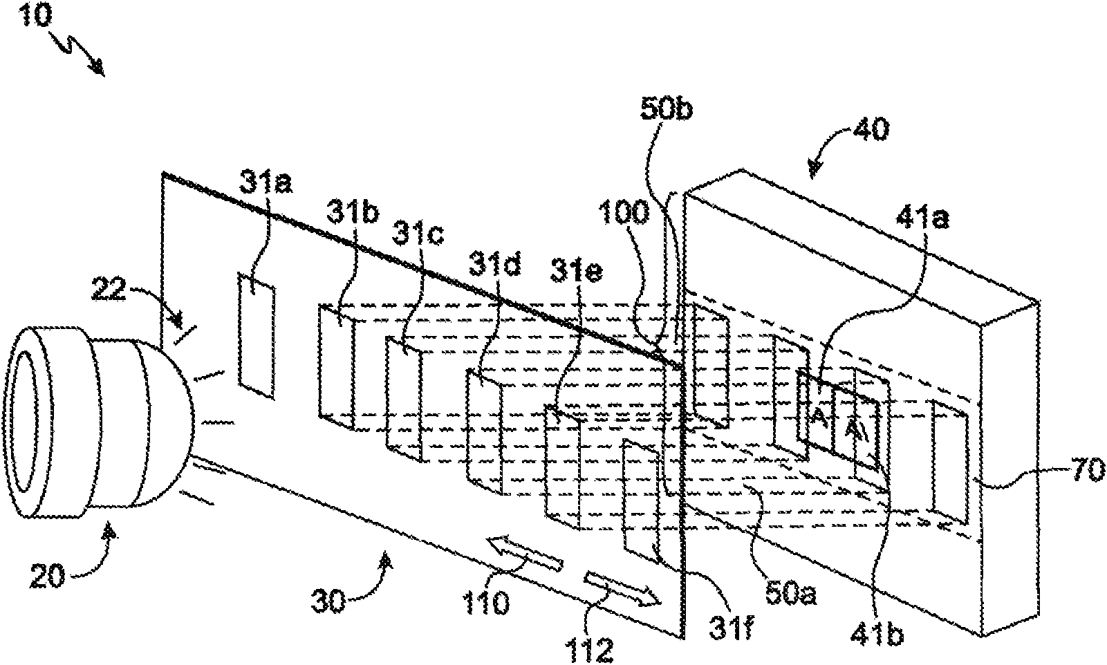
[0033] now refer to Figure 5 , illustrates one embodiment of a portion of an optical encoder 10 that includes a light emitter configured to emit a light beam 22 therefrom. Figure 5 A light beam 22 is shown incident on a collimating lens 24 which collimates the light beam 22 to form a collimated light beam 26 which is then incident on a code strip or code wheel 22, The code strip or the code wheel 22 is configured to move along an axis that coincides with the movement directions 111 and 112 . Note that collima...


PUM


Abstract

The invention provide high resolution optical encoder systems, devices and methods. Disclosed are various embodiments of front-end analog circuitry for use in conjunction with optical encoders. Highly accurate analog output signals are provided by front-end analog circuitry in incremental or absolute motion encoders to interpolation circuitry, which is capable of providing high interpolation factor output signals having high timing accuracy. The disclosed interpolation circuits may be implemented using CMOS or BiCMOS processes without undue effort.

Description

technical field [0001] Various embodiments of the invention described herein relate to the field of motion encoders, and interpolation circuits, assemblies, devices, systems and methods associated therewith. Background technique [0002] Interpolation circuits are often used in incremental and absolute digital motion encoding systems, where the interpolation circuit is configured to generate digital pulses having a higher frequency than the underlying sinusoidal analog signal input to the circuit. Since the output provided by such an interpolation circuit ultimately determines the accuracy of the encoding system, the accuracy of the interpolation circuit becomes more critical as the interpolation factor of the circuit increases. Unfortunately, due to the architecture of most interpolation circuits (which typically rely on a large number of comparators), the output provided by the interpolation circuit tends to be noisy and contains unwanted noise due to excessive switching i...

Claims


Application Information

Patent Timeline
Patent Type & Authority Applications(China)
IPC IPC(8): G01D5/347
CPCH03M1/303H03M1/206
Inventor 李彦伟
Owner AVAGO TECH WIRELESS IP SINGAPORE PTE
Learn More