
Plane cross slip ring for scroll compressor

A technology of scroll compressors and Oldham slip rings, which is applied to components of pumping devices for elastic fluids, rotary piston machinery, rotary piston/swing piston pump components, etc., and can solve the problem of scroll compressors. Increased noise and vibration, shortened service life of the compressor, harmful vibration and noise, etc., to achieve the effect of eliminating noise, prolonging working life and improving working conditions

Inactive Publication Date: 2012-09-05
XI AN JIAOTONG UNIV
View PDF0 Cites 0 Cited by
  • Summary
  • Abstract
  • Description
  • Claims
  • Application Information

AI Technical Summary

Problems solved by technology

The result is increased noise and vibration in the scroll compressor and shortened compressor life
At the same time, it is precisely because of the existence of these four keys that the Oldham slip ring is likely to repeatedly collide between the end plate of the movable scroll and the end plate of the fixed scroll during the working process, causing periodic tilting vibration noise
Not only does this shorten the life of the compressor, it also emits unwanted vibrations and noises constantly

Method used


Image

  • Plane cross slip ring for scroll compressor
  • Plane cross slip ring for scroll compressor
  • Plane cross slip ring for scroll compressor

Examples


Embodiment Construction

[0030] The present invention is described in further detail below in conjunction with accompanying drawing:

[0031] see Figure 1-12 , although the principles of the present invention can be applied to many different types of scroll machines, but for the sake of illustration, a hermetic scroll compressor is described here.

[0032] Referring to the drawings below, in all the drawings, the same reference numerals represent the same components or faces of the components in all the drawings. Figure 7 A schematic cross-sectional view of a scroll compressor is shown in , which includes a unique planar Oldham slip ring according to the present invention, and is indicated by reference numeral 14 . The scroll compressor includes a compressor middle casing 22, a lower casing 24, an upper casing 26, a bracket 17, and the bracket is fixed in the compressor middle casing 22; the fixed scroll 15 is fixed in the compressor casing; the moving scroll The turntable 13 cooperates with the f...


PUM


Abstract

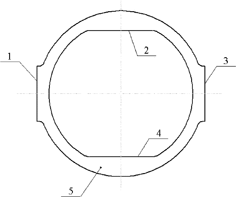
The invention discloses a plane cross slip ring for a scroll compressor. The plane cross slip ring is in a plane layout structure; working main bodies are two pairs of lug bosses crossly arranged on the plane cross slip ring; the spatial position of a working plane is positioned between two end planes of the plane cross slip ring; one pair of the lug bosses arranged on the plane cross slip ring are positioned at the excircle side of the plane cross slip ring, and the other pair of the lug bosses are positioned at the inner circle side of the plane cross slip ring; the working planes of the lug bosses are mutually perpendicular; the working planes of the first pair of the lug bosses of the plane cross slip ring are attached to the friction surfaces of a pair of lug bosses of a static scroll plate, and the working planes of the second pair of the lug bosses are attached to the friction surfaces of a pair of lug bosses of a dynamic scroll plate; and the working planes of the lug bosses of the plane cross slip ring, the friction surfaces of the dynamic scroll plate and the friction surfaces of the static scroll plate are all parallel to a central axis of the plane cross slip ring, thus the dynamic scroll plate takes plane circular motion under the driving of a bent axle. The invention effectively solves the problems of vibration, noise and short life of the traditional cross slip ring without a protruding guide slide block of the traditional cross slip ring.

Description

Technical field: [0001] The invention relates to the field of scroll machinery. In particular, the present invention relates to a unique flat Oldhams slip ring used in these scroll machines. Background technique: [0002] Such machines, commonly referred to in the art as "scroll" machines, are used for the transport of various types of fluids. This scroll machine can be made into a scroll expander, a scroll compressor, a scroll engine, a scroll pump and the like. The features of the present invention are suitable for any of these machines. However, for purposes of illustration, the disclosed embodiments are in the form of hermetic refrigerant scroll compressors. [0003] Scroll compressors are increasingly used as compressors in refrigeration and air conditioning applications. Generally, a scroll compressor is mainly composed of a movable scroll, a fixed scroll, an Oldham slip ring, a bearing housing, a crankshaft, a motor, a sealed casing, and the like. A scroll arrang...

Claims


Application Information

Patent Timeline
Patent Type & Authority Patents(China)
IPC IPC(8): F04C29/00F04C18/02
Inventor 吴华根李星星齐井文宋晶唐昊邢子文
Owner XI AN JIAOTONG UNIV
Learn More