Driving mechanism of retarding motor

A driving mechanism and deceleration motor technology, applied in the direction of motors, motor vehicles, electric vehicles, etc., can solve the problems of large lateral size, large vehicle volume, heavy weight, etc., and achieve reduced axial size, simple and compact structure, and low cost Effect

Inactive Publication Date: 2012-10-03
DONGGUAN ROBSTEP ROBOT
View PDF0 Cites 0 Cited by
  • Summary
  • Abstract
  • Description
  • Claims
  • Application Information

AI Technical Summary

Problems solved by technology

[0003] In the current self-balancing two-wheeled electric vehicles, the reducer mechanism is placed on both sides of the vehicle body, which makes the lateral size of the vehicle large, and usually a tower-type deceleration structure makes the vehicle large in size and heavy in weight.

Method used


Image

  • Driving mechanism of retarding motor
  • Driving mechanism of retarding motor

Examples


Embodiment Construction

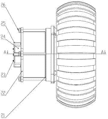
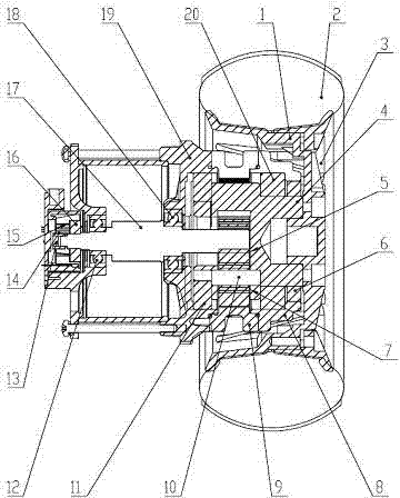
[0021] Such as figure 1 and figure 2 As shown, the geared motor drive mechanism of the present invention includes a brushless motor, a planetary reducer and a hub mechanism assembled into one; wherein the brushless motor includes a motor shaft (17), and two bearings installed at both ends of the motor shaft (17) (12) and (18), a position sensing magnet (16) fixed at the non-output end of the motor shaft (17), an encoder magnet (13) installed at the non-output end of the motor shaft (17), and a Install the aluminum tube (14) of the encoder magnet (13), a spacer (15), a motor end cover (19), a motor rear cover (22), and 3 pieces are evenly distributed on the Hall fixing frame (24) Hall sensor (23), an encoder Hall plate (25) installed at the end of the motor, a Hall fixing frame (24) and 4 pan head screws (26) used to connect the motor and reducer.

[0022] The planetary reducer includes 3 bearings (6), (11) and (20) installed at both ends of the output shaft (4), one output ...


PUM


Abstract

The invention discloses a retarding mechanism with a hub and a brushless motor, relating to a retarding mechanism on a self-balanced two-wheel electromobile, comprising a brushless motor, a hub mechanism and a planetary reducer, wherein the brushless motor, the hub mechanism and the planetary reducer are assembled into a whole; the brushless motor is in transmission connection with the planetary reducer; the hub mechanism comprises an inner hub, an outer hub and a tyre, wherein the inner hub and the outer hub are provided with connection lugs inserted in a groove of the tyre; and the planetary reducer is inserted on the inner hub and comprises an output shaft, a plurality of planet gears, a plurality of bearings installed on the output shaft, a reducer end cover and an inner gear ring meshed with the planet gear, wherein the output shaft is connected with the inner hub in a flange connection manner. The retarding mechanism has the advantages of reasonable design, compact and simple structure, high transmission efficiency, low noise and long service life.

Description

technical field [0001] The invention relates to a geared motor driving mechanism, in particular to a geared motor driving mechanism used in a self-balancing two-wheeled electric vehicle. Background technique [0002] Self-balancing two-wheeled electric vehicle is a kind of electric vehicle with tires arranged in parallel on the left and right, and adopts the principle of inverted pendulum to realize self-balancing electric vehicle; it uses the built-in gyroscope and acceleration sensor in the vehicle body to detect the transformation of the center of gravity between the human body and the vehicle, so as to control the vehicle The direction and speed of the motor, the high speed output by the motor is transformed into an appropriate low speed through the reducer, which requires the reducer to realize the speed change stably and accurately. [0003] In the current self-balancing two-wheeled electric vehicles, the reducer mechanism is placed on both sides of the vehicle body, w...

Claims


Application Information

Patent Timeline
Patent Type & Authority Patents(China)
IPC IPC(8): B62M7/12B62M11/14H02K7/116H02K29/08
CPCY02T10/641Y02T10/64
Inventor 闫学凯周伟胡志诚
Owner DONGGUAN ROBSTEP ROBOT
Why Eureka
Try Eureka