Automatic tin cutting machine

A tin-cutting and automatic technology, applied in the directions of tin-feeding devices, auxiliary devices, metal processing equipment, etc., can solve the problem of not having the function of tin-cutting

Inactive Publication Date: 2011-05-18
厦门顺拓电子有限公司
View PDF5 Cites 3 Cited by
  • Summary
  • Abstract
  • Description
  • Claims
  • Application Information

AI Technical Summary

Problems solved by technology

like figure 1 As shown, the commonly used tin-discharging machine 1' only delivers the tin wire 2' to the operator, and does not have the function of cutting tin

Method used


Image

  • Automatic tin cutting machine
  • Automatic tin cutting machine
  • Automatic tin cutting machine

Examples


Embodiment Construction

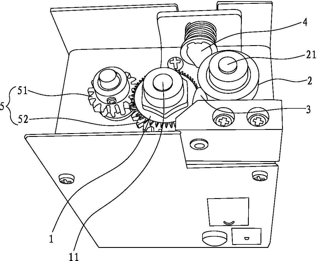
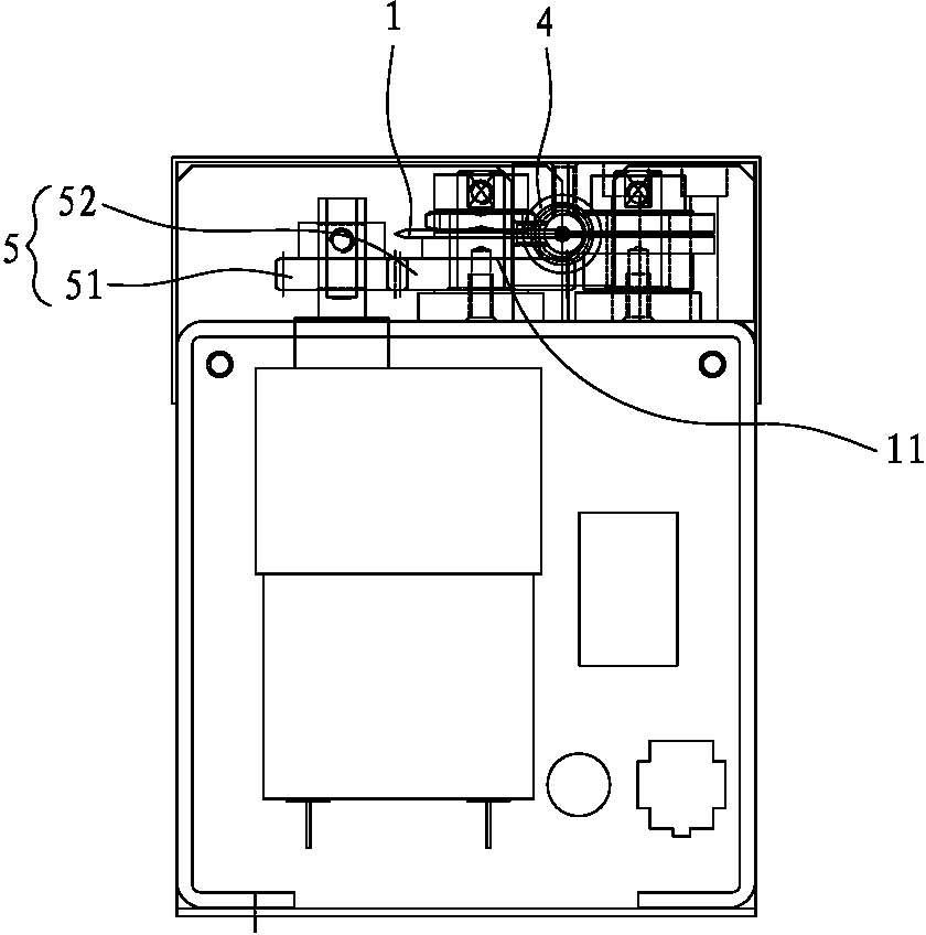
[0019] Such as figure 2 As shown, the present invention is an automatic tin cutting machine, which is mainly composed of a cutting gear blade 1, a guide wheel 2, a tin nozzle pipe 3, a tin feeding head 4, and a transmission mechanism 5.

[0020] Such as figure 2 , Figure 6 As shown, the cutting gear blade 1 is set opposite to the guide wheel 2, and is respectively rotatably sleeved on the gear blade rotating shaft 11 and the guiding wheel rotating shaft 21. The circumference of the guide wheel 2 is provided with a shallow groove 22 around the entire circumference, and the radial line of the shallow groove 22 is on a horizontal plane with the radial line of the cutting gear blade 1, so that the cutter teeth of the cutting gear blade 1 are aligned. To the shallow groove 22 on the guide wheel 2, and the gap between the cutter tooth of the cutting gear blade 1 and the shallow groove 22 on the guide wheel 2 is smaller than the tin wire diameter, so that the cutter teeth of the...


PUM


Abstract

The invention discloses an automatic tin cutting machine which mainly comprises a cutting gear blade, a guide wheel, a tin outlet nozzle pipe and a tin inlet head, wherein the cutting gear blade is arranged opposite to the guide wheel, a shallow groove surrounding the circumference is arranged on the circumference of the guide wheel, cutter teeth of the cutting gear blade are arranged opposite to the shallow groove arranged on the guide wheel, the tin outlet nozzle pipe is opposite to the tin inlet head, a half-edge groove is arranged on the mesopore wall of the tin outlet nozzle pipe along the longitudinal direction, and the cutter teeth of the cutting gear blade cuts over the half-edge groove so as to split a tin wire in the tin outlet nozzle pipe. Because the tin wire between the cutting gear blade and the guide wheel is cut through the cutting gear blade, and a cutter tooth angle of the cutting gear blade is reasonably designed, the automatic tin cutting machine can well drive the tin wire to move forwards and can also efficiently prevent the wire adhesion phenomenon caused by the cutter teeth of the cutting gear blade, which excessively cut over the tin wire, therefore, the invention has the advantages of high automation degree and good tin cutting effect.

Description

technical field [0001] The invention relates to a welding device, in particular to an automatic tin cutting machine. Background technique [0002] With the popularity of lead-free soldering, a large number of lead-free tin wires are used. During high-temperature soldering, the flux in the tin wire will expand and volatilize, while the inside of the tin wire is in a sealed state, and the volatilization of the flux will burst out from the solder joints, forming Fried tin. If the tin wire is pierced, the volatilization of the flux will volatilize from the pierced hole, so it can reduce tin frying. Therefore, an automatic tin cutting machine is designed to automatically remove tin and puncture the tin wire. During high-temperature soldering, the flux will volatilize from the punctured tin wire hole after heating, eliminating the splash of lead-free tin wire during high-temperature soldering. , Improve welding quality and PCB surface quality. Such as figure 1 As shown, the co...

Claims


Application Information

Patent Timeline
IPC IPC(8): B23K3/06B23K3/08
Inventor 陈志忠
Owner 厦门顺拓电子有限公司
Why Eureka
Try Eureka