
Push rod type underwater mud scraper

A technology of mud scraper and push rod type, which is applied in the direction of chemical instruments and methods, separation methods, sedimentation separation, etc., can solve the problems of sludge churning, increased energy consumption of devices, and easy breakage of steel wire ropes, etc., and achieves high processing efficiency and conception Sophisticated, high-strength effects

Inactive Publication Date: 2011-05-18
JIANGSU TIANHONG ENVIRONMENTAL ENG
View PDF3 Cites 12 Cited by
  • Summary
  • Abstract
  • Description
  • Claims
  • Application Information

AI Technical Summary

Problems solved by technology

Sometimes, some suspended decanting devices, aeration devices, etc. may be installed in the middle of the pool, which makes it very inconvenient to operate when scraping mud.
In addition, when the whole device is running in water, there is a phenomenon of "stirring water". First, the resistance of the water will increase the energy consumption of the device. Second, when the water is stirred by a large movement, it will cause the settled sludge to churn and reduce the treatment effect.
In addition, due to the aging of the structure and other reasons, the steel wire rope is particularly easy to break. When it is overhauled, it is necessary to stop the water intake and stop the production of the water plant, which affects the normal operation of the water plant.

Method used


Image

  • Push rod type underwater mud scraper
  • Push rod type underwater mud scraper
  • Push rod type underwater mud scraper

Examples


Embodiment Construction

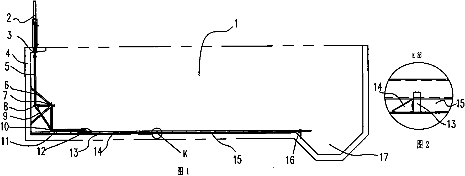
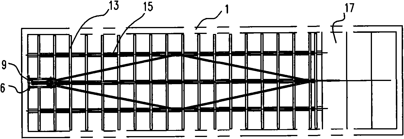
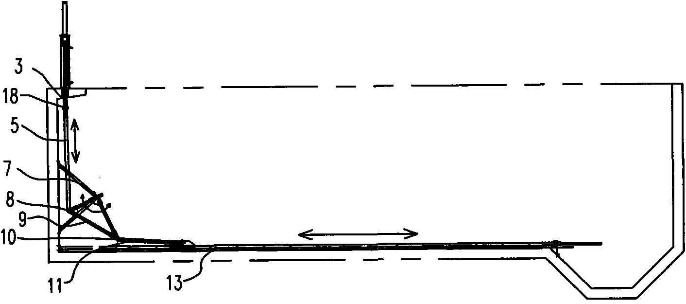
[0016] The present invention as Figure 1-3 As shown, it is set in the sedimentation tank 1 as a whole, and one end of the sedimentation tank 1 is provided with a sludge tank 17. The mud scraper includes a scraper 13, a driving device and a transmission mechanism, and the driving device is fixed on the sedimentation tank 1. On the pool edge at the other end away from the sludge tank 17, the transmission mechanism is provided on the pool wall 4 at this end; the transmission mechanism includes a support 6, a transmission frame 9, a push rod 11, a push rod seat 12, a scraper Plate frame 15 and slat 14 with a wedge-shaped section (scraper 13 and slat 14 can be designed in one, forming a scraper assembly with a wedge surface), and the support 6 is fixedly connected to the end tank The position of the midline in the horizontal direction of the lower part of the wall 4, the transmission frame 9 is triangular, one of the corners of the transmission frame 9 is hinged with the support 6...


PUM


Abstract

The invention discloses a push rod type underwater mud scraper, and relates to an underwater mud scraping device. The underwater mud scraper for underwater step operation does not occupy the space of a tank and has low stirring to water. The underwater mud scraper is arranged in a sedimentation tank, and one end of the tank is provided with a sludge trough; the mud scraper comprises a scraping plate, a driving device and a transmission mechanism; the driving device is fixed on the edge of the other end of the sedimentation tank far from the sludge trough, and the transmission mechanism is arranged on the tank wall of the end; the transmission mechanism comprises a support, a transmission rack, a push rod, a push rod seat and a scraping plate basket; the scraping plate is provided with an oblique wedge surface facing the tank wall, the support is fixedly connected at the central line position of the lower middle part of the tank wall of the end, the transmission rack is triangular, one corner of the transmission rack is hinged with the support, the other two corners of the transmission rack close to the tank wall are connected with the driving device, and the corner of the transmission rack close to the tank bottom is hinged with the push rod; the scraping plate basket is longitudinally arranged relative to the sedimentation tank, and the scraping plate is transversely and fixedly connected on the scraping plate basket; and the push rod seat is fixedly connected on the scraping plate basket and hinged with the other end of the push rod. The underwater mud scraper has skilful design and high processing efficiency.

Description

technical field [0001] The invention relates to an underwater mud scraping device in an inclined plate tube advection sedimentation tank in a water treatment process, mainly for removing sludge deposited at the bottom of the tank. Background technique [0002] The mud scraper used in the inclined plate tube sedimentation tank generally adopts the wire rope traction underwater mud scraper at home and abroad. When this mud scraper performs mud scraping operations, in order to drive the only scraper to move longitudinally along the bottom of the pool, the wire rope traction mechanism needs to move synchronously along the longitudinal direction of the pool on the upper part of the pool. Sometimes, some suspended decanting devices, aeration devices, etc. may be installed in the middle of the pool, which makes the operation very inconvenient when scraping mud. In addition, when the whole device is running in water, there is a phenomenon of "stirring water". First, the resistance ...

Claims


Application Information

Patent Timeline
Patent Type & Authority Applications(China)
IPC IPC(8): B01D21/20
Inventor 徐时红戴家旗姚能栋戴明发
Owner JIANGSU TIANHONG ENVIRONMENTAL ENG
Learn More