
Soft-decision method and signal receiving system thereof

A receiving system and soft decision technology, applied in the field of data processing, can solve problems such as quantization distortion, increase bit error rate, affect decoder, etc., and achieve the effect of increasing coding gain and reducing bit error rate

Inactive Publication Date: 2013-06-12
MSTAR SOFTWARE R&D (SHENZHEN) LTD +1
View PDF3 Cites 0 Cited by
  • Summary
  • Abstract
  • Description
  • Claims
  • Application Information

AI Technical Summary

Problems solved by technology

Therefore, if the three are divided into N equal parts, it will cause distortion during quantization and affect the judgment of the decoder, resulting in a decrease in coding gain, and an increase in the bit error rate due to the inability to accurately correct error bits. (bit error rate, BER)

Method used


Image

  • Soft-decision method and signal receiving system thereof
  • Soft-decision method and signal receiving system thereof
  • Soft-decision method and signal receiving system thereof

Examples


Embodiment Construction

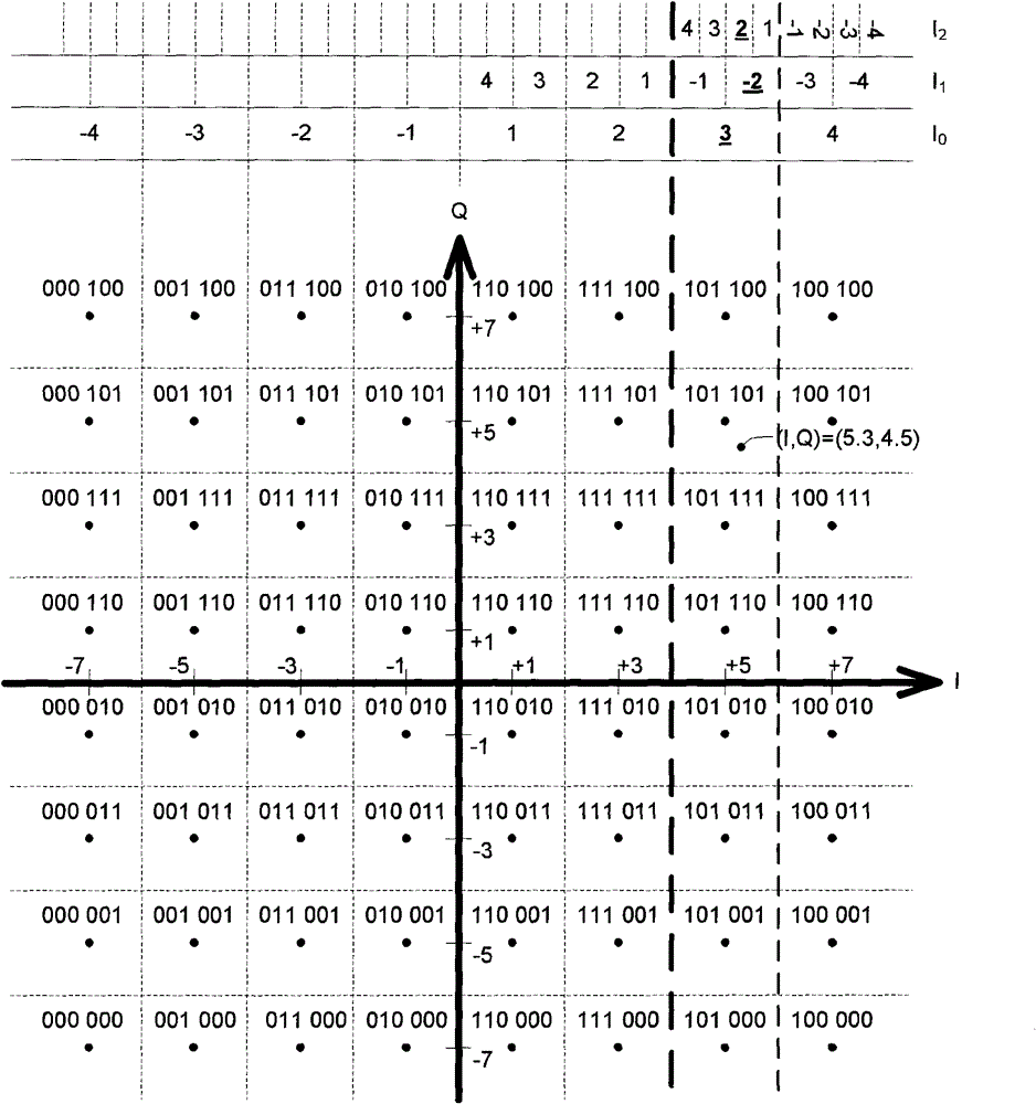
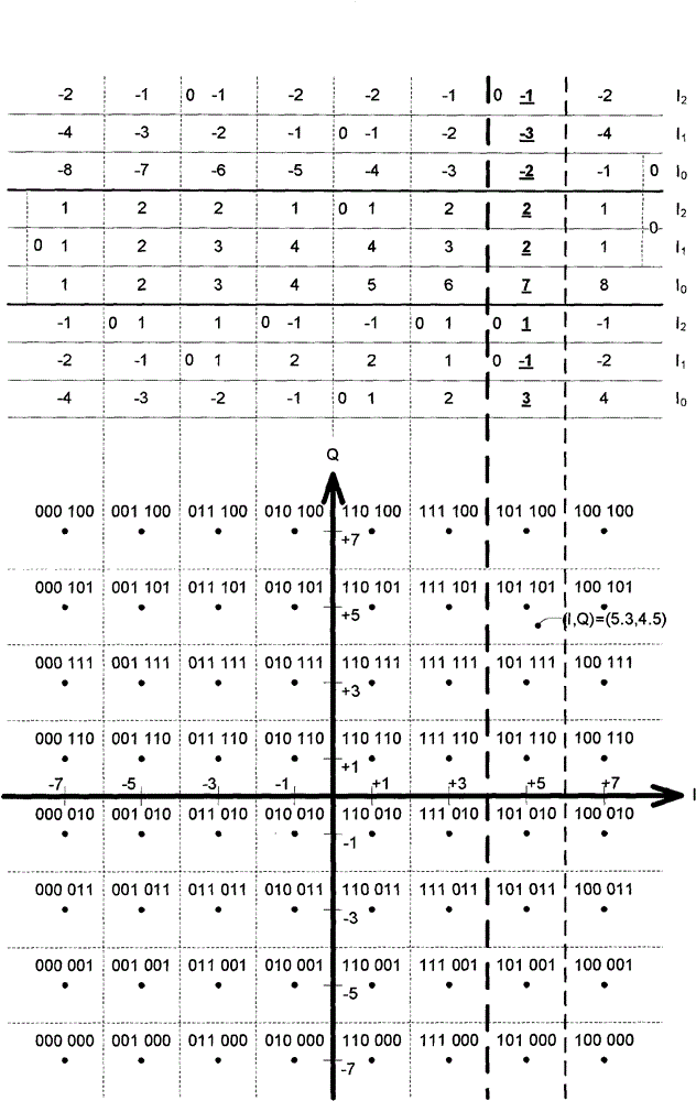
[0025] image 3 It is a 64QAM star diagram according to an embodiment of the present invention. Figure 4 It is a functional block diagram of a signal receiving system 40 according to an embodiment of the present invention, including: a signal restorer 440 , an inverse mapper 460 and a decoder 480 . The signal restorer 440 receives an input signal and converts the input signal into a multi-signal 5.3+4.5j. The multi-signal can represent a coordinate value, which can be regarded as image 3 A coordinate (5.3, 4.5) on the middle star diagram, where 5.3 is the I coordinate value, and 4.5 is the Q coordinate value.

[0026] The inverse mapper 460 is coupled to the signal restorer 440 for inversely mapping the I and Q coordinate values ​​into (I 0 , I 1 , I 2 , Q 0 , Q 1 , Q 2 ) coordinates, I 0 , I 1 , I2 , Q 0 , Q 1 and Q 2 Coordinates can have boundary values. In a preferred embodiment, since the signal restorer 440 actually receives the signal due to the influence ...


PUM


Abstract

The invention relates to a soft-decision method and a signal receiving system thereof, and is used for determining a soft-decision coordinate related to a star graph . The soft-decision coordinate comprises a first soft-decision sub-coordinate and a second soft-decision sub-coordinate. The soft-decision method comprises the following steps: receiving an input signal containing a coordinate value;defining a first coordinate scope having a first boundary value and a second boundary value on a coordinate axis of the star graph; acquiring the first soft-decision sub-coordinate according to the first coordinate scope, defining a second coordinate scope having a third boundary value and a fourth boundary value on the coordinate axis of the stellulate diagram, and acquiring the second soft-decision sub-coordinate according to the first coordinate scope, wherein the first and third boundary values and the second and fourth boundary values are not the same at the same time.

Description

technical field [0001] The present invention relates to a data processing method in a communication system, in particular to a soft decision method for inverse mapping of a communication system. Background technique [0002] figure 1 It is a functional block diagram of an existing signal receiving system 10 , including a signal restorer 140 , a demapper (demapper) 160 and a decoder 180 . The inverse mapper 160 includes a mapping function corresponding device 164 and a quantizer 167 . [0003] The signal restorer 140 receives the input signal and converts the original input signal corresponding to the time domain into a set of inphase signal (inphase signal, I signal for short) and quadrature signal (quadrature signal, Q signal for short) corresponding to the frequency domain. The inverse mapper 160 generates digital data corresponding to the I and Q signals according to the constellation applied to the input signal. For example, the modulation modes corresponding to binar...

Claims


Application Information

Patent Timeline
Patent Type & Authority Patents(China)
IPC IPC(8): H04L27/34H04L25/03
Inventor 洪绍评庄景翔何天行
Owner MSTAR SOFTWARE R&D (SHENZHEN) LTD
Learn More