Clutch electric control mechanism for vehicle

A control mechanism and clutch technology, applied to clutches, mechanical equipment, vehicle components, etc., can solve problems such as low transmission efficiency and large drive motor power, reduce motor power, reduce power and volume, and facilitate vehicle integration and installation and layout effects

Inactive Publication Date: 2011-05-11
TONGJI UNIV
View PDF0 Cites 1 Cited by
  • Summary
  • Abstract
  • Description
  • Claims
  • Application Information

AI Technical Summary

Problems solved by technology

In the existing electric control mechanism, the transmission mechanism with reverse self-locking function such as screw nut or worm gear is generally used. Its advantage is that it can realize reverse self-locking without adding auxiliary mechanisms, but the disadvantage is that the transmission efficiency is low. Requires larger drive motor power

Method used


Image

  • Clutch electric control mechanism for vehicle
  • Clutch electric control mechanism for vehicle
  • Clutch electric control mechanism for vehicle

Examples


Embodiment 1

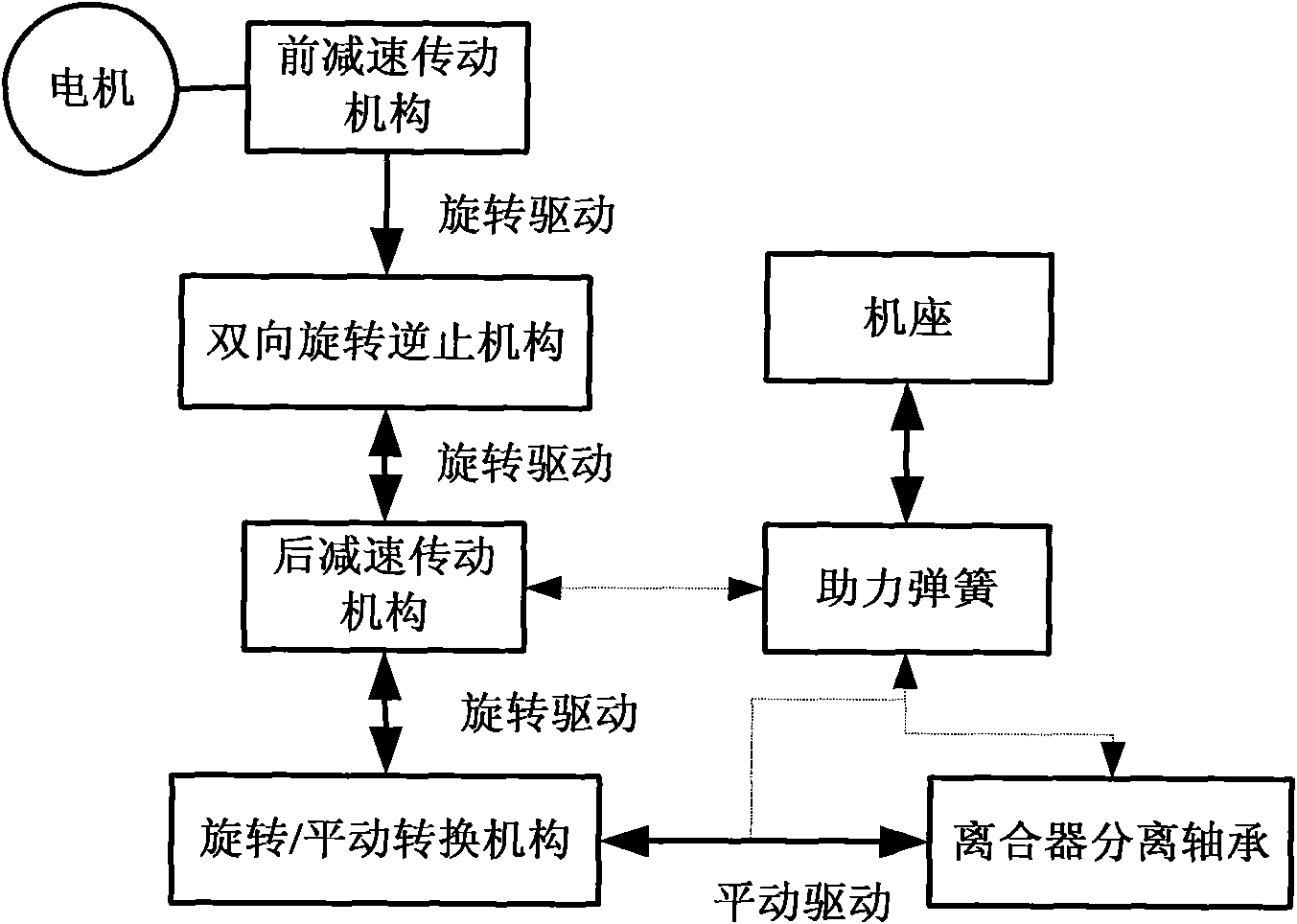
[0018] A vehicle clutch electric control mechanism, its working principle is as follows: figure 1 As shown, the mechanism includes a drive motor, a two-way rotation backstop mechanism, a front deceleration transmission mechanism, a rear deceleration transmission mechanism and a rotation / translation conversion mechanism. The drive motor is connected to the two-way rotation backstop mechanism through the front deceleration transmission mechanism. The transmission mechanism adopts a fixed-axis structure, and the rotation / translation conversion mechanism and the bidirectional rotation check mechanism are connected through a rear reduction transmission mechanism. The rear reduction transmission mechanism adopts a planetary gear structure, and the rotation / translation conversion mechanism adopts a ball screw structure. The translation conversion mechanism also separates the clutch through the clutch release bearing, and a one-way booster spring is also arranged between the two-way ro...

Embodiment 2

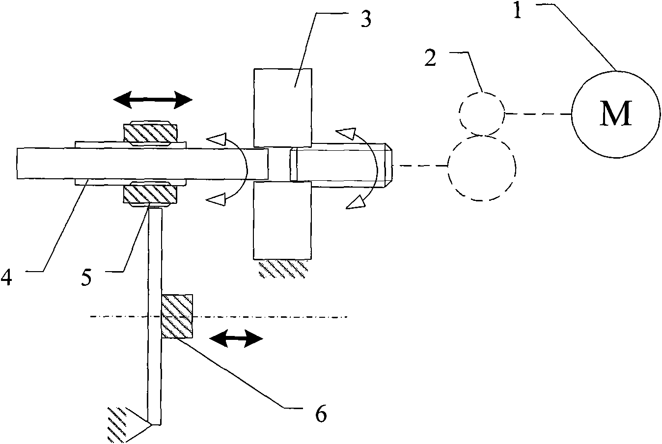
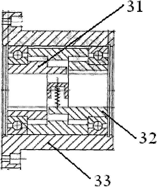
[0021] A high-efficiency vehicle clutch electric control mechanism, the specific structure is as follows figure 2 As shown, it includes a driving motor 1, a gear meshing pair 2, a two-way sprag overrunning clutch 3, a ball screw 4, a ball screw nut 5, and a clutch release bearing 6. The rotor of the drive motor 1 drives the driving gear connected to the gear meshing pair 2, and the driven gear of the gear meshing pair 2 is connected to the input shaft drive 31 of the two-way wedge overrunning clutch 3, and the gear meshing pair 2 can be configured as a multi-stage fixed shaft as required Common forms such as gear reduction or planetary gear reduction; the output shaft of the two-way sprag overrunning clutch 3 drives 32 to connect the lead screw 4 of the ball screw, thereby converting the rotational motion into the translational motion of the nut 5, and the nut 5 further translates to drive the clutch The release bearing 6 realizes the separation and combination of the clutch....


PUM


Abstract

The invention relates to a clutch electric control mechanism for a vehicle, and the mechanism comprises a driving motor, a bilateral rotation back stop mechanism, a front underdrive mechanism, a rear underdrive mechanism and a rotation / translation switching mechanism, wherein the driving motor is connected with the bilateral rotation back stop mechanism through the front underdrive mechanism; the rotation / translation switching mechanism is connected with the bilateral rotation back stop mechanism through the rear underdrive mechanism; and the rotation / translation switching mechanism carries out separation operation on the clutch through a clutch release bearing. Compared with the prior art, the invention has the advantages that after the bilaterial back stop mechanism is arranged, non-self-locking transmission pairs such as a high-efficient gear / ball screw and the like can be adopted to serve as a transmission mechanism, and the power of the driving motor can be reduced obviously.

Description

technical field [0001] The invention relates to a clutch operating mechanism, in particular to an electric clutch operating mechanism for a vehicle. Background technique [0002] The automatic control mechanism of the automobile clutch has a wide range of applications and is an indispensable part of the automatic mechanical transmission (AMT). [0003] The operating mechanism of the dry diaphragm clutch is mainly divided into hydraulic, pneumatic and electric types. In recent years, electric operating mechanisms have become more and more popular. Compared with hydraulic and pneumatic operating mechanisms, the advantages of electric mechanisms are low cost, convenient control, and convenient system integration. But its disadvantage is that it needs a transmission mechanism to convert the high-speed rotational motion of the motor into the translational motion required for manipulation. A basic requirement for the electric clutch operating mechanism is to have a reverse self...

Claims


Application Information

Patent Timeline
Patent Type & Authority Applications(China)
IPC IPC(8): F16D48/06B60K23/02
Inventor 钟再敏陈辛波吴海康林宵马勇高智
Owner TONGJI UNIV
Why Eureka
Try Eureka