
Electrically-driven bearing/gear mounting device capable of adjusting height and angle

An installation device and electric drive technology, which is applied in hoisting devices, metal processing, metal processing equipment, etc., can solve problems such as low work efficiency and poor safety performance, and achieve the effects of easy operation, guaranteed stability, and smooth operation

Inactive Publication Date: 2011-05-11
TIANJIN SANXIN SUNSHINE
View PDF6 Cites 2 Cited by
  • Summary
  • Abstract
  • Description
  • Claims
  • Application Information

AI Technical Summary

Problems solved by technology

Although it can be lifted and lowered during the hoisting process, the angle cannot be rotated, so the bearing cannot be installed in place accurately and quickly, the work efficiency is low, and the safety performance is poor

Method used


Image

  • Electrically-driven bearing/gear mounting device capable of adjusting height and angle
  • Electrically-driven bearing/gear mounting device capable of adjusting height and angle
  • Electrically-driven bearing/gear mounting device capable of adjusting height and angle

Examples


Embodiment Construction

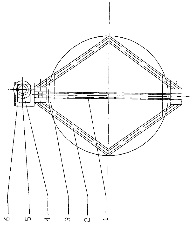
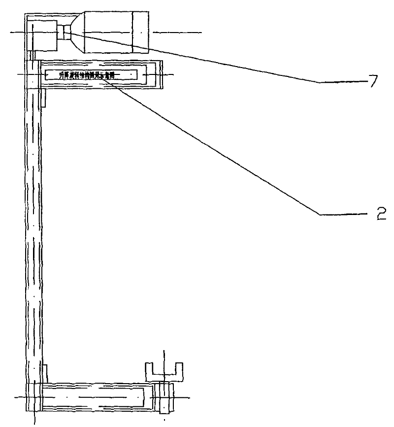
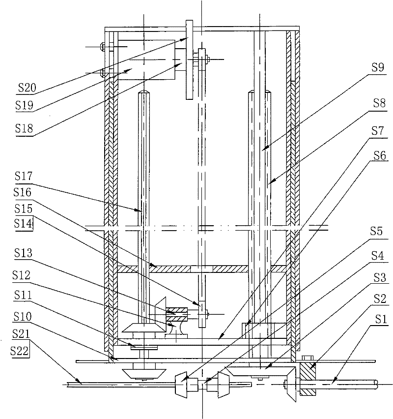
[0017] As shown in the figure: an electrically driven adjustable height and angle bearing / gear installation device, the lifting and rotating device 2 is respectively installed on the top and bottom of the rhombus chassis 1, and the lower part of the rhombus chassis is equipped with a fixed plate S10; the lifting and rotating The device is composed of a transmission mechanism, a rotating mechanism, a lifting mechanism and a bearing clamping device.

[0018] The transmission mechanism is composed of a motor 3 and a worm gear reducer 4 , and the motor and the worm gear reducer are fixed on a support plate 5 and connected by a coupling 6 . The main bevel gear set is installed on the worm shaft of the reducer, and the bevel gear A is installed on the transmission shaft; the two lifting and rotating devices at the top and bottom of the rhombus chassis are connected through the transmission shaft.

[0019] The rotating mechanism is composed of a feed rod, a bevel gear B installed at ...


PUM


Abstract

The invention relates to an electrically-driven bearing / gear mounting device capable of adjusting the height and angle. Lifting rotating devices are installed at the top end and the bottom end of a diamond-shaped base plate respectively,; a fixing plate is installed below the diamond-shaped base plate; each lifting rotating device comprises a transmission mechanism, a rotating mechanism, a lifting mechanism and a bearing clamping device; the transmission mechanism comprises a motor and a worm gear and worm speed reducer, wherein a master bevel gear set is installed on a worm connecting shaft of the speed reducer, and a bevel gear A is installed on the transmission shaft; the two lifting rotating devices at the top end and the bottom end of the diamond-shaped base plate are connected through the transmission shaft; the rotating mechanism comprises a feeding rod, a bevel gear B installed at the bottom of the feeding rod, and a bevel gear C installed on the fixing plate; the lifting mechanism comprises a guide rod, a leading screw installed on the guide rod and bevel gears D installed at the bottoms of the guide rod and the leading screw respectively; the bevel gears D are connected with the bevel gear A; and the bearing clamping device is connected with the bevel gear B. The electrically-driven bearing / gear mounting device can be used for adjusting the angle and height of the bearing during the process of installation at any moment and is time-saving and labor-saving.

Description

Technical field: [0001] The invention belongs to a kind of mechanical equipment, in particular to an electrically driven adjustable height and angle bearing / gear installation device. Background technique: [0002] Whether the bearing is installed well or not affects the accuracy, life and performance of the bearing. At present, the installation of large bearings with a diameter of more than 2 meters and a weight of 1 ton mainly depends on hoisting tools for hoisting and installation. Although it can be lifted during the hoisting process, it cannot rotate the angle, so the bearing cannot be installed in place accurately and quickly, the work efficiency is low, and the safety performance is poor. Invention content: [0003] The purpose of the present invention is to overcome the deficiencies in the above-mentioned prior art, and provide an electrically driven height-adjustable and angle-adjustable bearing / gear installation device, which can adjust the angle and height of th...

Claims


Application Information

Patent Timeline
Patent Type & Authority Applications(China)
IPC IPC(8): B23P19/00B66F11/00
Inventor 曹润星李卫华李凤元王永兴
Owner TIANJIN SANXIN SUNSHINE
Learn More