
Method for assembling a socket for a discharge lamp and discharge lamp

A technology for discharge lamps and lamp caps, which is applied in the manufacture of discharge tubes/lamps, discharge lamps, high-pressure discharge lamps, etc., and can solve problems such as high cost of lamp caps

Inactive Publication Date: 2011-05-04
OSRAM GMBH
View PDF3 Cites 0 Cited by
  • Summary
  • Abstract
  • Description
  • Claims
  • Application Information

AI Technical Summary

Problems solved by technology

Therefore, during the manufacture of discharge lamps, the assembly of the lamp base is cost-intensive

Method used


Image

  • Method for assembling a socket for a discharge lamp and discharge lamp
  • Method for assembling a socket for a discharge lamp and discharge lamp
  • Method for assembling a socket for a discharge lamp and discharge lamp

Examples


Embodiment Construction

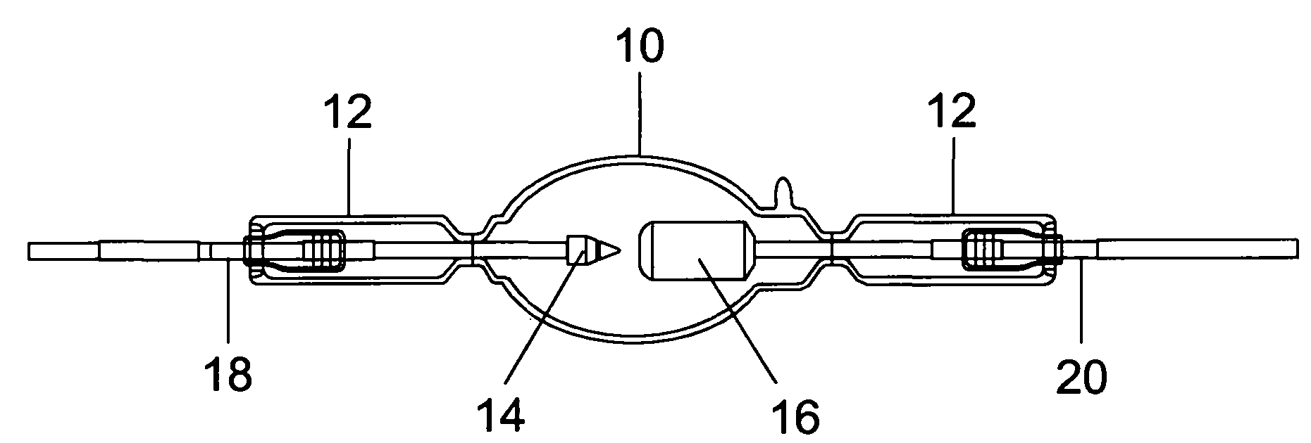
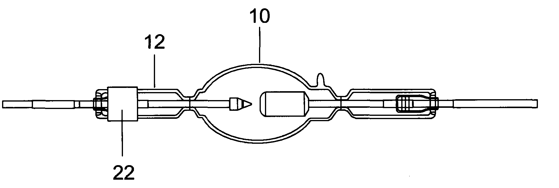
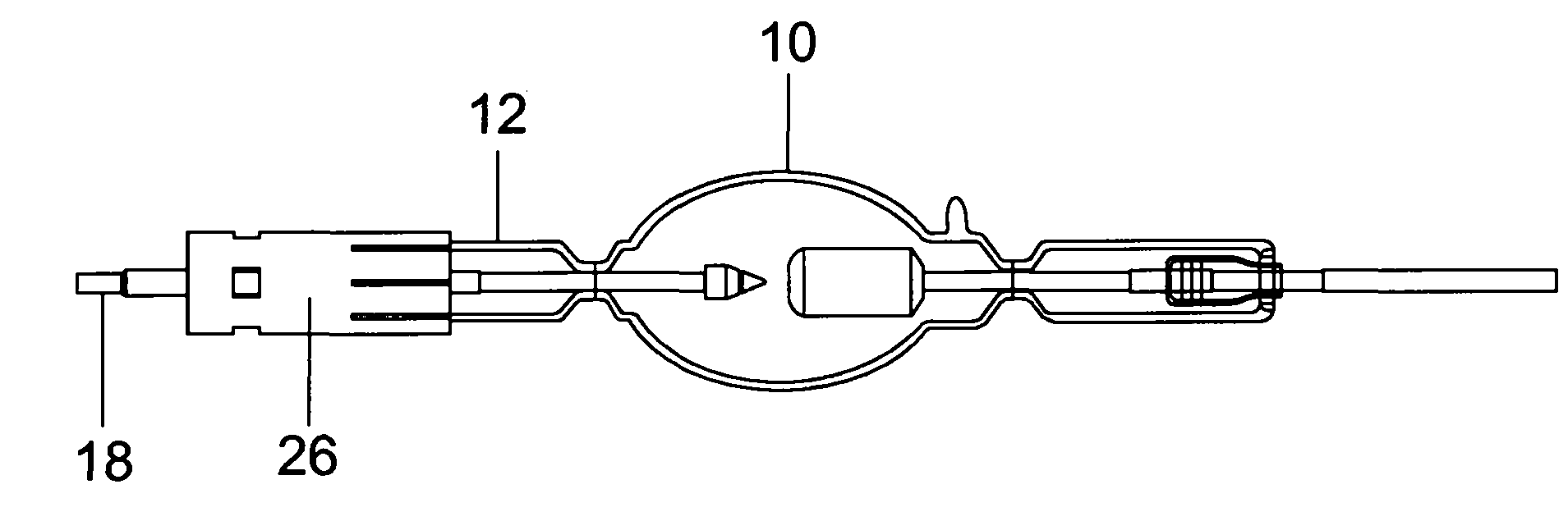
[0019] The method according to the invention is based on the Figure 1A High-pressure discharge lamp under manufacture in the state shown. After the discharge vessel 10 has been produced from glass or quartz glass with two cylindrical handles 12 connected on opposite sides, this state is obtained in the following manner by The electrode holding rods 18 and 20 are welded in each case in order to serve as an external connection for the electrodes, ie to provide contact possibilities with the electrodes. Electrode holding rods 18 and 20 protrude from the cylindrical shaft 12 , ie the two end regions of the discharge vessel 10 . A lamp cap will now be provided, by means of which the high-pressure discharge lamp can be inserted into a lampholder. Electrical contact with the electrode holding pin 18 or 20 will be established via the lamp cap. In the method described below, a single cap is applied to the discharge vessel 10 . Usually, a lamp cap is mounted on each of the two rod-...


PUM


Abstract

The invention relates to mounting a socket sleeve (26) on a shaft (12) designed as the end region of a discharge vessel (10), wherein a clamp ring (34) is used for pressing on the socket sleeve, said ring comprising at least one seam (36). A force fit of the socket sleeve on the discharge vessel is thereby ensured. The seam compensates for individual differences in the shape of the shaft (12) of the discharge vessel, whereby excessive application of force to the shaft (12) is optionally prevented. In the same manner, as an additional measure, it can be provided that a graphite ring (22) set on the shaft (12) is provided beneath the socket sleeve (26). The graphite ring (22) can have slits and a wave profile.

Description

technical field [0001] The invention relates to a method for assembling a base for a discharge lamp according to the preamble of claim 1 or 6 and a discharge lamp according to the preamble of claim 9 . Background technique [0002] A method for assembling a base for a discharge lamp according to the preamble of claim 1 or 6 is generally known. After manufacturing the discharge vessel with the electrodes placed therein, and after the electrode holding rods are welded on the electrodes located in the discharge vessel, so that the electrode holding rods can protrude, for example, from the end regions of the discharge vessel as external connections, providing A discharge vessel in the form of an uncapped lamp. Now, the lamp cap cannot be mounted on the discharge vessel without difficulty, because the shape of the end region of the discharge vessel is not perfectly adapted to the lamp cap. Therefore, before the base cap is mounted on the end region, a material serving as a cush...

Claims


Application Information

Patent Timeline
Patent Type & Authority Applications(China)
IPC IPC(8): H01J5/60H01J9/34H01J5/54H01J61/86
CPCH01J9/34H01J5/54H01J5/60H01J61/86
Inventor 斯文-乌韦·巴克格哈德·莱夫勒迪尔克·罗森塔尔沃尔夫冈·塞茨
Owner OSRAM GMBH
Learn More